

close
Choose Your Site
Global
Social Media

Views: 0 Author: Site Editor Publish Time: 2026-08-06 Origin: Site


Inadequate tank venting creates massive physical and financial liabilities. Bulk liquid storage facilities face constant threats of catastrophic structural failure. Roof rupture or tank implosion happens rapidly if internal pressure exceeds design limits. Furthermore, fugitive emissions from poorly sealed tanks trigger severe regulatory fines. Engineers often refer to a breather valve as a Pressure/Vacuum Relief Valve (PVRV) or a conservation vent. Understanding this interchangeable nomenclature helps during technical procurement. Facility operators must balance strict environmental regulations regarding volatile organic compound (VOC) emission limits against physical realities. Tanks must breathe during thermal changes and fluid transfers. They require continuous pressure equalization without losing valuable product. Specifying the correct valve serves as an engineering safeguard. This guide evaluates selection criteria, operational mechanics, and compliance frameworks necessary for proper technical procurement.
Dual Protection: A properly specified breather valve mitigates both internal overpressure (from thermal expansion or filling) and vacuum conditions (from cooling or emptying), preventing tank deformation.
Emission, Loss, and Content Control: By remaining closed until a precise pressure threshold is reached, these valves minimize vapor loss and prevent atmospheric moisture or oxygen from degrading the stored product, directly impacting profitability and environmental compliance.
Specification Complexity: Selecting the right storage tank breather valve requires rigorous adherence to standards like API 2000/ISO 28300, factoring in flow rates, set pressures, and chemical compatibility.
Environmental Adaptability: Harsh climates necessitate specialized equipment, such as an all weather breather valve, to prevent mechanical freezing and ensure uninterrupted safety.
Storage tanks appear robust from the outside, but they operate under strict structural limitations. Most flat-bottom atmospheric tanks are built to API 650 standards. They hold the massive static weight of liquid perfectly, but they handle internal pressure poorly. A standard API 650 tank might have a Maximum Allowable Working Pressure (MAWP) of just a few inches of water column (inWC). The design vacuum limit is often even lower. Exceeding the MAWP causes the roof-to-shell frangible seam to tear open. Dropping below the design vacuum causes the massive steel shell to buckle inward like a crushed soda can. A properly specified storage tank breather valve prevents both of these catastrophic scenarios by maintaining internal pressure within a safe, narrow band.
The baseline expectation for tank safety is continuous pressure equalization. The valve must flow enough vapor to keep the internal pressure below the MAWP during the absolute worst-case overpressure event. Conversely, it must draw in enough air or blanketing gas to keep the internal pressure above the design vacuum limit during the worst-case underpressure event. Success means the tank shell never flexes, the roof never tears, and normal operational breathing occurs without excessive product loss.
Tank breathing happens continuously. Operational activities and weather patterns drive these internal pressure fluctuations. The valve responds mechanically to these changes without requiring external power or instrumentation.
Pump-in operations rapidly displace the vapor space inside the tank. If you pump in 1,000 gallons of liquid per minute, you force 1,000 gallons of vapor per minute to compress. Simultaneously, thermal out-breathing occurs during peak daylight hours. Solar radiation heats the steel tank shell, causing the internal vapor to expand significantly. This combined effect increases internal pressure. The pressure pallet inside the valve reacts to this upward force. Once the internal pressure overcomes the pallet's calibrated weight, the assembly lifts off the seat. The valve vents the excess vapor safely into the atmosphere or routes it into a vapor recovery header. The pallet reseats immediately once the internal pressure drops back below the set point.
Pump-out operations create the exact opposite effect. Extracting liquid expands the available vapor space. Thermal in-breathing compounds this issue during sudden weather changes. A rapid summer rainstorm can cool a heated tank shell by 40 degrees in ten minutes. The internal vapor contracts violently. This rapid contraction creates a dangerous vacuum. Atmospheric pressure pushes heavily against the external tank shell. The vacuum pallet inside the valve senses this negative internal pressure. The heavier external atmospheric pressure lifts the vacuum pallet off its seat. The valve draws in ambient air or inert blanketing gas. This action equalizes the pressure and prevents the tank from imploding.
Open venting allows unrestricted vapor escape. This approach guarantees massive product loss through continuous evaporation. Controlled venting changes the economic equation entirely. The valve remains tightly sealed during normal resting conditions. It only opens during active fluid transfer or extreme thermal events. This tight seal drastically reduces product evaporation. Facilities save thousands of gallons of valuable liquid annually. Furthermore, the closed system prevents atmospheric moisture ingress. Airborne debris, insects, and oxygen cannot enter the tank freely. This preserves product purity and prevents internal corrosion. The initial investment in high-quality venting equipment pays for itself rapidly through recovered product alone.
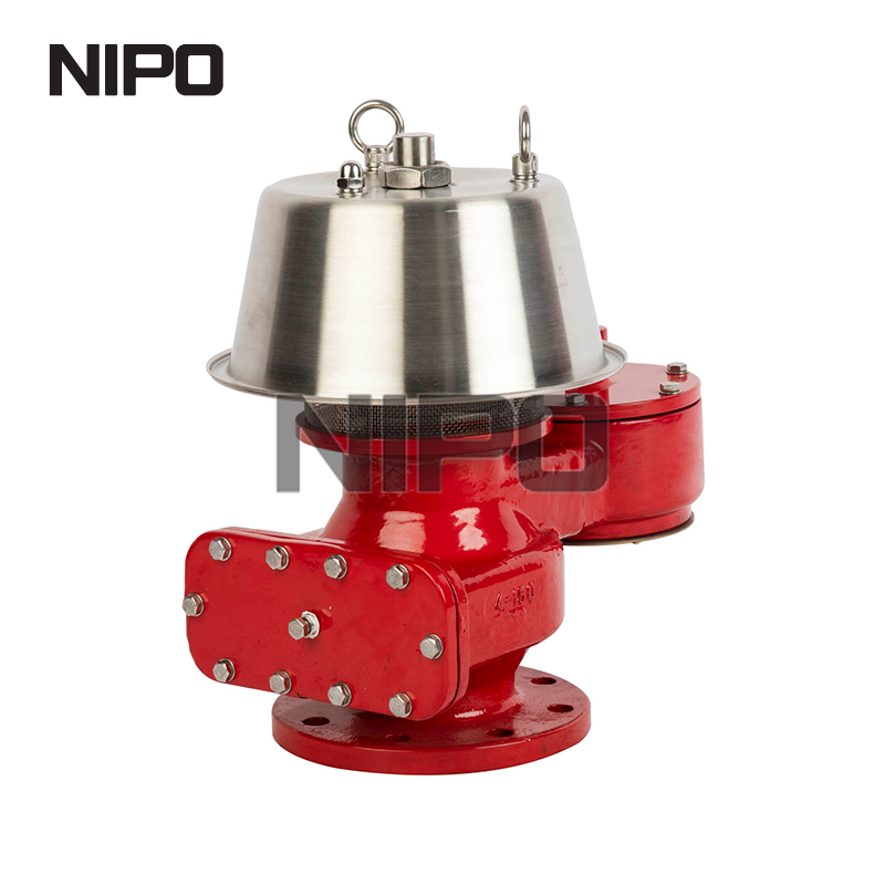
Engineers must match the valve mechanism to the specific tank design. Different operational pressures demand distinct mechanical solutions. Selecting the wrong type leads to premature wear, inadequate sealing, or total mechanical failure.
Weight-loaded valves represent the industry standard for low-pressure applications. The mechanism relies on simple gravity. Technicians place calibrated lead or stainless steel weights on top of the sealing pallet. These weights hold the pallet firmly against the machined valve seat. The seal remains intact until internal pressure exceeds the combined weight of the pallet assembly.
These units offer exceptional reliability due to their simple design. They contain minimal moving parts. Maintenance crews can inspect them easily on the tank roof by manually lifting the pallets. Weight-loaded models serve best on standard atmospheric storage tanks. They handle standard vapor control where operating pressures remain very low (typically under 1 psi). However, they become impractically heavy and physically massive if high set pressures are required.
Spring-loaded valves utilize adjustable spring tension instead of gravity weights. A compressed spring pushes the sealing pallet against the seat. Technicians adjust the spring compression using a threaded bolt to set the precise opening pressure. This design handles much higher pressure settings than weight-loaded equivalents, making them suitable for tanks built to API 620 standards.
This mechanism offers distinct trade-offs. Spring-loaded valves provide excellent protection for higher-pressure vessels. They resist vibration and pulsation better than weight-loaded models. However, springs exhibit a proportional opening characteristic. The valve requires a wider pressure variation to achieve full lift. We call this extra pressure requirement "accumulation." The valve may begin to simmer or leak slightly before reaching the full open position. Engineers must account for this accumulation when sizing the unit to ensure the tank MAWP is not exceeded before the valve fully opens.
Pilot-operated valves utilize a completely different mechanical philosophy. They use the actual tank pressure to maintain a tight seal. A small pilot valve controls the main valve diaphragm. As internal pressure rises, the pilot directs this pressure to push the main sealing pallet harder against the seat. The seal actually becomes tighter as pressure increases.
Once the pressure reaches the exact set point, the pilot actuates. It vents the pressure holding the main pallet closed. The main valve snaps open fully and instantly. This design is ideal for applications requiring operation very close to the tank's MAWP. It guarantees minimal leakage and maximum vapor conservation, often remaining bubble-tight up to 98% of the set pressure. The primary drawbacks involve higher initial costs and increased maintenance complexity. The tiny pilot sensing lines require clean vapor; dirty or crystallizing media will plug the lines and cause the valve to fail closed.
Procurement requires strict adherence to engineering data. Guesswork leads directly to structural failure or regulatory violations. Engineers evaluate three primary dimensions before specifying a unit for field installation.
API 2000 and ISO 28300 outline the mandatory engineering frameworks for sizing. These standards dictate exactly how much vapor the valve must flow under worst-case scenarios. Undersizing restricts flow and breaks the tank. Oversizing causes valve chattering and rapid mechanical destruction.
Maximum Pump-In Rates: Determine the absolute highest liquid flow rate entering the tank. The valve must vent the displaced vapor instantly.
Maximum Pump-Out Rates: Identify the fastest liquid extraction rate. The vacuum side must draw in replacement gas at an equal volumetric rate to prevent implosion.
Thermal Variations: Calculate the maximum temperature swing for the specific geographic location. Rapid cooling dictates the thermal in-breathing requirement, while solar radiation dictates thermal out-breathing.
Flash Point and Volatility: Highly volatile liquids flash into vapor rapidly during filling. This requires larger venting capacities compared to heavy, stable oils.
The valve body and internal trim must survive constant exposure to the stored media. Incorrect materials degrade rapidly. Corroded seats leak constantly. Degraded pallets stick shut and cause tank rupture. You must match the metallurgy and the elastomers to the chemical properties of the vapor.
Material Type | Common Applications | Key Advantages |
|---|---|---|
Aluminum | Standard petrochemicals, clean fuels | Lightweight, cost-effective, non-sparking, easy to install |
Carbon Steel | Heavy oils, non-corrosive chemicals | High durability, standard industrial use, impact resistant |
316 Stainless Steel | Corrosive chemicals, food grade, pharma | Excellent general corrosion resistance, easily polished |
Hastelloy / Alloy 20 | Highly aggressive acids, toxic media | Superior resistance to pitting, cracking, and severe chemical attack |
PTFE / FEP Coatings | Sticky media, extreme cold environments | Prevents adhesion, resists ice buildup, provides ultimate chemical barrier |
Elastomer selection is equally critical. Selecting proper O-rings and diaphragms ensures a bubble-tight seal. Buna-N works well for standard oils and ambient temperatures. Viton handles higher temperatures and specific aromatics. PTFE inserts provide ultimate chemical resistance but require higher seating forces to achieve a tight seal.
Geographic location heavily influences valve specification. Standard valves fail in extreme environments. Moisture in the vented vapor condenses on the valve seat. In freezing temperatures, this condensation turns to solid ice. The ice bonds the pallet to the seat. The tank cannot breathe and subsequently ruptures during the next pump-in cycle.
Regions prone to freezing temperatures require an all weather breather valve. These specialized units incorporate specific anti-freezing features. Look for FEP or PTFE coated pallets and flexible diaphragms that prevent ice adhesion. Specialized weather hoods keep blowing snow and freezing rain away from the moving components. In extreme sub-zero climates, facilities utilize steam-jacketed or electrically traced valve bodies. These active heating elements guarantee the seats remain ice-free year-round.
Different industrial sectors face unique regulatory and operational challenges. Valve configurations adapt to meet these specific sector demands. A one-size-fits-all approach does not work in bulk liquid storage.
Refineries manage massive volumes of highly volatile and flammable liquids. A breather valve for petroleum and petrochemical storage tanks must integrate seamlessly with other safety systems. These valves rarely vent directly to the atmosphere due to strict VOC emission laws enforced by environmental agencies.
Engineers pipe the valve exhaust into Vapor Recovery Units (VRU) or flare headers. This requires closed-vent, flanged configurations. Furthermore, these tanks often utilize inert gas blanketing. The vacuum side of the valve draws in nitrogen instead of atmospheric air. This prevents explosive oxygen mixtures from forming inside the vapor space. Explosion-proof designs and integrated flame arresters are mandatory. The flame arrester sits directly below the valve. It utilizes a crimped metal ribbon element to quench the flame front, stopping external fires from flashing back into the tank.
Chemical plants store highly reactive, toxic, or corrosive substances. Standard aluminum or carbon steel valves dissolve quickly in these environments. Facilities require highly specialized, corrosion-resistant tank vent breather valve configurations to handle aggressive off-gassing.
Engineers specify Hastelloy, Monel, or fully PTFE-lined valve bodies. Toxic vapors cannot vent locally on the tank roof. Pipe-away designs capture the exhaust and route it to chemical scrubbers or thermal oxidizers. The sealing requirements are exceptionally stringent. Even minor fugitive emissions pose severe health hazards to plant personnel. Pilot-operated valves frequently serve chemical applications due to their superior bubble-tight sealing capabilities and precise opening tolerances.
Sanitary applications prioritize cleanliness over extreme pressure handling. A breather valve for tank installations in these industries must prevent biological contamination. Standard industrial valves contain crevices, threads, and rough castings where bacteria multiply rapidly.
Sanitary valves feature highly polished 316L stainless steel surfaces with specific Ra (roughness average) values. They utilize tri-clamp connections instead of standard industrial flanges for quick removal. The internal design must be fully self-draining. This ensures clean-in-place (CIP) and sterilize-in-place (SIP) compatibility. The vacuum side often incorporates sterile filters. When the tank draws in air during pump-out, the filter removes airborne microbes. This protects the purity of the food, beverage, or pharmaceutical product.
Procuring the correct valve solves only half the problem. Improper installation or neglected maintenance guarantees eventual failure. Field execution requires strict protocols and experienced personnel.
Valve placement dictates maintenance success. Breather valves require routine physical inspection. Engineers must position them strategically on the tank roof. Technicians need safe, flat access platforms. Installing a valve near an unprotected roof edge creates severe fall hazards. If a valve is difficult to reach, maintenance crews will ignore it. Ensure clear access for lifting equipment. Large cast-iron or steel valves are incredibly heavy. Technicians cannot safely carry them up vertical cage ladders. Provide proper flanged connections that mate perfectly with the tank nozzle. When bolting an aluminum valve to a steel flange, technicians must use a star-pattern torquing sequence. Uneven bolting warps the soft aluminum base, permanently distorting the valve seat and causing endless leaks.
Sizing errors manifest quickly in the field. Undersizing is the most dangerous error. The valve cannot flow enough vapor during a rapid pump-out or sudden rainstorm. The tank pulls a vacuum and collapses inward. Oversizing causes different mechanical problems. An oversized valve opens slightly, vents the pressure instantly, and slams shut. It repeats this cycle rapidly. This phenomenon is called "chattering." Chattering destroys the valve seats, damages the pallets, and leads to continuous fugitive emissions. You must size the valve for the actual operational flow, not just the theoretical maximum of the pipe diameter.
Field technicians encounter several recurring issues during routine operations. Identifying these failure modes early prevents catastrophic tank damage.
Pallet Sticking: Stored product vapors can crystallize on the valve seat. In cold weather, condensation freezes. The pallet bonds to the seat and refuses to open during a pressure event.
Seat Damage: Chattering or abrasive particulates in the vapor stream scratch the precisely machined seats. This damage breaks the seal and causes continuous vapor leakage.
Blockage: Birds or insects build nests inside the weather hoods. Airborne debris clogs the protective bird screens. This blockage restricts flow capacity and renders the valve useless.
Corrosion: Incorrect material specification leads to rapid internal rusting. Moving parts seize completely, locking the valve in a closed position.
Proactive maintenance ensures operational trustworthiness. Establish a baseline for routine inspection intervals based strictly on API 2000 guidelines and local environmental conditions.
Conduct visual inspections every three to six months. Check the weather hoods for debris. Verify the protective screens remain clear. Look for visible signs of external corrosion or base flange leakage. Perform comprehensive bench testing annually. Remove the valve from the tank using proper lifting gear. Transport it to a clean maintenance shop. Mount it on a calibrated test bench equipped with a rotameter and a water manometer. Verify the exact set pressure for both the pressure and vacuum pallets. Measure the leak rate just below the set point to ensure it meets factory specifications. Replace all elastomer seals, diaphragms, and gaskets before reinstalling the unit on the tank roof.
Protecting bulk storage infrastructure requires rigorous engineering discipline and proactive field management. Take the following immediate actions to secure your storage assets:
Compile your tank design data, specifically the Maximum Allowable Working Pressure (MAWP) and maximum design vacuum limits.
Calculate your exact thermal and operational flow requirements using the latest API 2000 guidelines based on your maximum pump rates.
Audit your existing roof installations for signs of chattering, seat leakage, or environmental degradation.
Consult with a specialized valve manufacturer to finalize precise sizing, material selection, and elastomer compatibility for your specific media.
A: There is no functional difference. "Conservation valve" or "conservation vent" is simply another industry term for a Pressure/Vacuum Relief Valve (PVRV). The term highlights the equipment's role in conserving valuable product by minimizing evaporation and reducing fugitive emissions into the atmosphere.
A: Breather valves handle low-pressure, high-volume vapor flow required for daily atmospheric tank breathing. They operate in inches of water column. Standard safety relief valves handle high-pressure liquid or gas emergencies in heavily pressurized vessels, operating at much higher PSI ranges. They utilize completely different internal mechanics.
A: Sizing relies strictly on API 2000 or ISO 28300 standards. Engineers calculate the maximum required venting capacity by factoring in maximum liquid pump-in and pump-out rates, liquid flash points, and the maximum thermal expansion or contraction caused by local weather changes.
A: In cold climates, standard valves fail because internal condensation freezes on the seats. This ice bonds the pallet shut, leading to tank rupture or vacuum collapse. All-weather models utilize specialized coatings like PTFE and weather hoods to prevent ice accumulation and ensure continuous operation.
A: Industry standards recommend a visual external inspection every three to six months to check for debris or damage. A full removal and internal bench test to verify set pressures and leak rates should occur annually, depending on the service environment and local regulatory requirements.
A: Yes. Most standard Pressure/Vacuum Relief Valves (PVRVs) are dual-functioning. They house both a pressure-relieving pallet and a vacuum-relieving pallet within a single physical unit. This combined design manages both overpressure and underpressure conditions simultaneously while saving space on the tank roof.


