

close
Choose Your Site
Global
Social Media

Views: 0 Author: Site Editor Publish Time: 2026-10-15 Origin: Site


Processing, storing, or transporting flammable gases presents severe operational and safety risks across industrial facilities. A single ignition event can cause catastrophic equipment failure and loss of life without proper isolation. Engineers know they need explosion protection on their tanks and piping networks. However, mis-specifying a flame arrestor creates a false sense of security. Confusing deflagration with detonation or ignoring pressure drop leads to regulatory liability and potential system bottlenecks. Selecting the correct device requires a rigorous evaluation of combustion dynamics, piping layout, and maintenance accessibility. We will break down the technical criteria for specifying the right safety device for specific industrial applications. You must understand the exact chemical properties of your process media and the physical constraints of your piping to prevent a localized fire from becoming a facility-wide disaster.
Mechanism of Action: Flame arrestors do not extinguish fires chemically; they mechanically absorb and dissipate the heat of a flame front through a permeable matrix (quenching element), dropping the temperature below the auto-ignition point and breaking the combustion chain reaction.
Combustion Dynamics Dictate Selection: The choice between a deflagration flame arrestor and a detonation arrestor depends entirely on the flame's speed and pressure, which is dictated by the distance from the potential ignition source.
Placement Matters: An in line deflagration flame arrestor is engineered for closed piping systems, whereas end-of-line arrestors are strictly for atmospheric venting.
Maintenance is Critical: Fouling compromises both safety and flow capacity. Designs like the drawer type deflagration flame arrestor significantly reduce downtime during mandatory inspections and cleaning.
Flame quenching relies on basic thermodynamics and fluid mechanics. When a flammable mixture ignites, the resulting flame front expands rapidly down the pipe or out of the vessel. To stop this progression, the flame must pass through a quenching element. This element typically consists of tightly wound, crimped metal ribbons or dense wire mesh. These narrow passages create a massive surface area relative to the volume of the gas passing through them.
As the flame enters these narrow gaps, the metal absorbs the intense thermal energy. This rapid heat transfer cools the reacting gases. Once the gas temperature drops below its specific auto-ignition point, the combustion chain reaction breaks. The flame extinguishes instantly. Engineers define the maximum allowable width of these gaps using a metric called the Maximum Experimental Safe Gap (MESG). The MESG dictates exactly how tight the crimped ribbon must be to stop a specific chemical flame. If the gap is even a fraction of a millimeter too wide, the flame will slip through and continue its path of destruction.
Industrial facilities deploy these devices across three primary operational zones to isolate ignition sources from fuel sources.
Preventing external flames from entering atmospheric storage tanks: Lightning strikes, static discharge, or nearby facility fires can ignite vented vapors. An arrestor mounted on the tank vent stops that external fire from flashing back into the bulk storage volume.
Isolating internal ignition events: Vapor recovery units (VRUs) and manifolded piping networks transport highly volatile mixtures. If an ignition occurs within a pump or compressor due to mechanical friction or electrical failure, the arrestor prevents the flame from traveling down the pipe and destroying connected vessels.
Protecting combustion equipment: Flares, thermal oxidizers, and industrial boilers intentionally burn waste gases. Arrestors sit upstream of these burners to ensure the intentional fire never travels backward into the fuel supply lines during low-flow conditions.
Hazardous area safety standards mandate explosion protection across multiple sectors. Chemical and petrochemical processing plants rely on these devices to secure reactor vents and solvent recovery lines. Refineries install them on crude oil storage tanks and flare headers to manage off-gassing safely. Pharmaceutical manufacturing facilities use them to protect high-purity alcohol and volatile organic compound (VOC) handling systems, where even a minor static spark can trigger an explosion.
Beyond oil and gas, pulp and paper mills generate combustible turpentine vapors requiring isolation. Mining operations capture and transport explosive methane gas from underground shafts. Power generation facilities use them on hydrogen-cooled generator purge lines. Wastewater treatment plants rely heavily on these devices to safely route highly combustible anaerobic digester gas (biogas) to boilers or flares. Biogas contains high levels of methane and hydrogen sulfide, making it both explosive and highly corrosive.
Industry | Typical Combustible Gas | Primary Application | Risk Profile |
|---|---|---|---|
Petrochemical Refining | Ethylene, Propylene | Flare Headers, Storage Tanks | High Pressure, High Volume |
Wastewater Treatment | Methane (Biogas), H2S | Digester Vents, Boiler Feeds | Corrosive, Continuous Flow |
Pharmaceuticals | Ethanol, Methanol, VOCs | Solvent Recovery Units | High Purity, Static Risk |
Power Generation | Hydrogen | Generator Purge Lines | Extreme Flame Velocity |
Operators must view this equipment as a life-safety investment rather than a standard pipe fitting. The primary benefit remains the protection of personnel from fatal industrial accidents. A properly specified device stops a localized fire from escalating into a facility-wide catastrophe. You cannot put a price tag on preventing loss of life.
Furthermore, these devices shield expensive connected equipment from total destruction. Replacing a damaged blower, VRU compressor, or thermal oxidizer disrupts production for months while you wait for replacement parts. Preventing these explosions ensures continuous facility uptime. Finally, strict regulatory compliance avoids severe legal penalties, insurance premium hikes, and facility shutdowns imposed by safety authorities following an audit or near-miss incident.
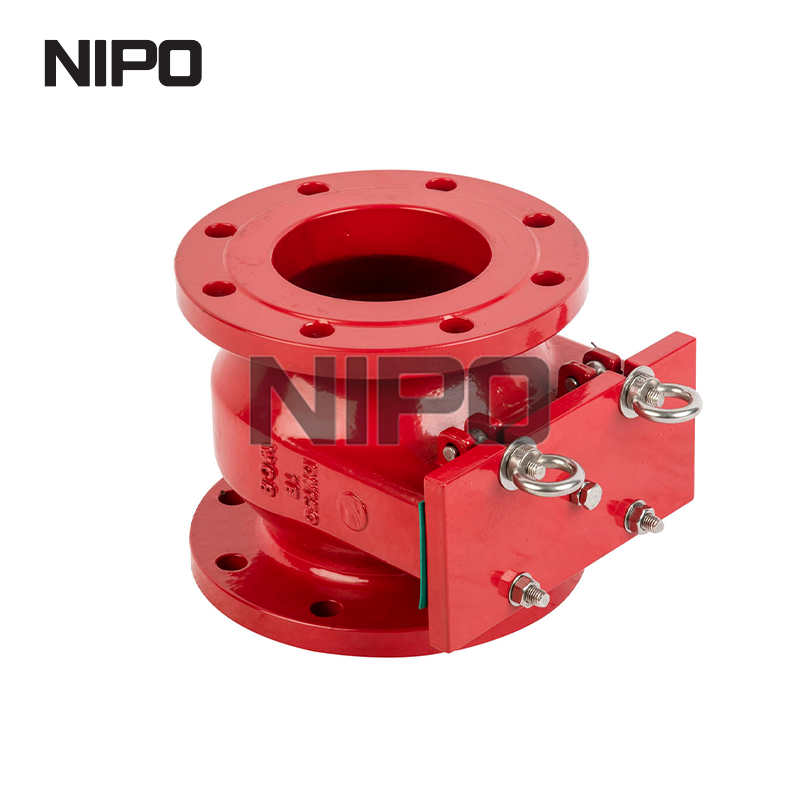
Deflagration describes a subsonic flame propagation. When a gas mixture ignites, the flame front travels slower than the speed of sound in the unreacted gas. The pressure wave stays relatively low, typically expanding at a manageable rate. Engineers specify a deflagration flame arrestor to handle these slower-moving, lower-pressure flame fronts. These devices feature quenching elements robust enough to absorb the heat of a deflagration but lack the structural mass required to survive a supersonic shockwave. You use them when the ignition source is close to the arrestor.
Detonation represents the worst-case combustion scenario. If a deflagration travels far enough down a pipe, the flame accelerates. The expanding hot gases push the unburned gas ahead of the flame, compressing it against the pipe walls and any bends. This pre-compression heats the unburned gas. Eventually, the flame front catches up to the pressure wave, transitioning into a detonation. A detonation travels at supersonic speeds, accompanied by a massive, destructive shockwave. Standard deflagration devices will fail catastrophically under detonation conditions. The shockwave will physically crush the crimped metal ribbon, allowing the flame to pass right through.
The distance between the potential ignition source and the arrestor determines the combustion threat level. Engineers calculate this using the Length to Diameter (L/D) ratio. You divide the straight pipe run length (L) by the pipe's internal diameter (D). A low L/D ratio means the flame has little room to accelerate, remaining a deflagration. A high L/D ratio means the flame will likely transition into a detonation.
For example, if you have a 2-inch diameter pipe and the ignition source is 100 inches away, your L/D ratio is 50. International standards provide strict L/D limits for deflagration devices based on the specific gas group. If your piping layout exceeds the allowable L/D ratio for a deflagration, you must upgrade to a detonation arrestor. Piping layout dictates this ratio, making it the absolute foundation of your specification process.
Closed piping systems require specific in-line configurations. You install an in line deflagration flame arrestor when the run-up distance from the ignition source remains short enough to guarantee subsonic flame speeds. Engineers flange these units directly into the process piping. Proper installation requires careful alignment to avoid putting undue stress on the arrestor housing, which could warp the internal quenching element.
Flow direction matters immensely. Bi-directional designs stop a flame front approaching from either side of the element. Uni-directional designs only protect against flames coming from one specific direction. Process lines with potential ignition sources on both ends, such as a manifold connecting two storage tanks, strictly require bi-directional protection. Always verify the flow arrow stamped on the housing before bolting the flanges together.
End-of-line units mount directly onto atmospheric vent nozzles. They never connect to downstream piping. Their sole purpose involves preventing environmental ignition sources from entering the vapor space of a vessel. Lightning strikes, static electricity, or adjacent equipment fires pose constant threats to vented vapors. These units typically feature a weather hood to prevent rain and snow from clogging the quenching element.
Facilities frequently integrate these units with Pressure/Vacuum (P/V) relief valves. The arrestor sits beneath the P/V valve. The valve maintains tank pressure and minimizes vapor loss, while the arrestor provides the physical barrier against external ignition when the valve lifts to vent. You must size the arrestor to handle the full venting capacity of the P/V valve without creating excessive backpressure.
Maintenance accessibility drives mechanical design innovations. A drawer type deflagration flame arrestor features a specialized housing. The quenching element, often called the bank or matrix, slides out of the housing laterally, exactly like a desk drawer. You do not need to unbolt the main pipe flanges or use heavy rigging equipment to spread the pipes apart to access the internals.
This configuration provides a massive operational advantage in the field. It allows technicians to perform rapid visual inspections and remove the element for cleaning. Minimizing process downtime saves money. More importantly, it protects maintenance personnel by reducing their time spent breaking flanges in hazardous, potentially toxic environments. You simply loosen the side cover bolts, slide the matrix out, inspect it against the light, and slide it back in.
Different chemicals burn at different temperatures and speeds. The specific chemical mixture dictates the required MESG of the quenching element. International standards categorize gases into specific groups based on their volatility and MESG requirements. You must know exactly what is flowing through your pipes.
Gas Group (IEC/ATEX) | Typical Reference Gas | MESG Range (mm) | Relative Hazard Level |
|---|---|---|---|
IIA | Propane, Methane | > 0.90 | Low to Moderate |
IIB3 | Ethylene | 0.65 - 0.90 | High |
IIC | Hydrogen, Acetylene | < 0.50 | Extreme |
Specifying a Group IIA arrestor for a Group IIC hydrogen process guarantees a catastrophic failure. The hydrogen flame will pass right through the wider gaps designed for methane. You must analyze the exact process gas composition before selecting the device. If you have a mixture of gases, you must size the arrestor for the most volatile component in the stream.
Standard arrestors carry certifications for atmospheric conditions. However, many process lines operate at elevated initial pressures and temperatures. Higher initial pressure creates a denser gas mixture, resulting in a much more violent explosion. Elevated initial temperatures pre-heat the unburned gas, making it easier for the flame to propagate through the quenching element. If your process exceeds standard atmospheric conditions, you must specify a device explicitly tested and certified for those exact elevated parameters. Do not assume a standard unit will hold up to a 50 PSI explosion.
Engineers face a constant trade-off between safety and process efficiency. Tighter quenching gaps provide superior explosion protection but create significant resistance to fluid flow. This resistance manifests as pressure drop across the device. Ignoring pressure drop leads to starved pumps, over-pressurized storage tanks, and reduced vapor recovery efficiency. You must consult the manufacturer's flow curves during the design phase.
To mitigate this, manufacturers design the arrestor housing to be significantly larger than the nominal pipe size. For example, a 4-inch pipe might connect to an arrestor with a 12-inch diameter quenching element. This expanded surface area allows the required volume of gas to pass through the tight crimped ribbons without causing an unacceptable pressure bottleneck. You will often use eccentric or concentric reducers to mate the large housing to your standard piping.
Sometimes, a flame does not just flash through a pipe; it stabilizes and burns continuously on the surface of the quenching element. This is called endurance burning. If left unchecked, the continuous heat will eventually melt the metal matrix, allowing the flame to pass through. Facilities mitigate this risk by integrating PT100 temperature sensors directly into the arrestor housing. If the sensor detects a stabilized flame, it immediately triggers a control system to shut down process flow, inert the line with nitrogen, or close isolation valves before the element fails.
Explosion protection devices require rigorous third-party testing. You cannot rely on theoretical calculations alone. Global regulatory frameworks dictate strict testing protocols to ensure true safety. ISO 16852 serves as the primary international standard for testing and classifying these devices. In Europe, the ATEX Directive 2014/34/EU mandates specific certification for equipment used in explosive atmospheres. You must look for the ATEX Ex stamp on the nameplate.
In North America, API 2000 governs venting requirements for atmospheric storage tanks, directly referencing arrestor integration. NFPA 69 outlines standards for explosion prevention systems. Engineers must ensure the selected device carries the appropriate certification stamps for the specific jurisdiction and application. Installing uncertified equipment leaves the facility open to massive liability in the event of an incident.
Process media corrosiveness dictates material selection. The housing and the internal quenching element must withstand the chemical environment without degrading. Rust or corrosion alters the precise geometry of the quenching gaps, instantly voiding the device's safety rating. A pitted quenching element cannot stop a flame.
Carbon steel housings work well for benign, dry gases. However, most chemical and petrochemical applications require 316L Stainless Steel for both the housing and the element to prevent corrosion. For highly aggressive media, such as wet hydrogen sulfide in biogas or hydrochloric acid vapors, engineers specify exotic alloys like Hastelloy or Duplex stainless steel. Environmental conditions, such as offshore salt spray, also influence external coating and material choices. Always match the metallurgy to your piping specification.
Process gases rarely flow perfectly clean. Particulates, pipe scale, moisture condensation, and chemical polymerization present severe operational challenges. These contaminants inevitably collect inside the microscopic passages of the quenching element. This accumulation is known as fouling. Vapor recovery lines handling heavy hydrocarbons are particularly susceptible to sticky, tar-like buildup. Biogas lines often suffer from moisture freezing in the gaps during winter months.
A clogged arrestor creates two distinct hazards. First, it chokes the process flow. As the gaps plug up, the pressure drop spikes, potentially over-pressurizing upstream vessels or tripping compressor safety interlocks. Second, and more dangerously, severe fouling alters the internal geometry of the matrix. If a flame event occurs, the altered gaps may fail to absorb enough heat, allowing the flame to propagate through the blockage. A neglected device completely negates its role as a safety barrier.
Proactive maintenance prevents catastrophic failures. Facilities must implement differential pressure monitoring across the arrestor. Installing pressure transmitters upstream and downstream allows the control system to track the pressure drop in real-time. A sudden or gradual increase alerts operators to fouling before it becomes critical. You can set alarms in your DCS to trigger maintenance work orders automatically.
Furthermore, plants must establish strict, time-based inspection protocols. Relying on run-to-failure strategies is unacceptable for life-safety equipment. Utilizing drawer-type configurations simplifies this compliance. Technicians can extract the element, clean it in an ultrasonic bath or with approved solvents, blow it out with compressed air, and reinstall it rapidly. This ensures the device remains clear and fully functional without requiring a crane or extensive pipefitting labor.
Calculate your exact Length to Diameter (L/D) ratio to determine if you need deflagration or detonation protection based on your piping layout.
Identify the specific gas group and MESG requirements of your process media to select the correct quenching element matrix.
Install differential pressure transmitters across the arrestor housing to monitor fouling and trigger maintenance alarms before flow is restricted.
Implement a mandatory, time-based inspection schedule utilizing ultrasonic cleaning baths to maintain the integrity of the quenching gaps.
A: Flashback arrestors are typically small, specialized devices used on welding and cutting gas lines to protect individual cylinders. Flame arrestors are large, industrial-scale devices engineered to protect process piping networks, vapor recovery units, and bulk storage tanks from massive deflagration or detonation events.
A: No. Using a deflagration device for a detonation event causes catastrophic failure. Detonations produce supersonic shockwaves and extreme pressures that will physically destroy the internal quenching element of a standard deflagration unit, allowing the flame to pass through.
A: It is an in-line safety device featuring a specialized housing with a removable element assembly. Maintenance personnel can slide the internal quenching matrix out laterally for rapid inspection and cleaning without breaking the main pipe connections or dismantling the entire spool.
A: Inspection frequency depends entirely on the process media's propensity to foul. Baseline recommendations require visual inspection at least annually. However, dirty or polymerizing processes may require monthly checks. Always inspect the unit immediately if differential pressure monitoring indicates an abnormal restriction.
A: The quenching gap is the precisely engineered microscopic distance between the metal plates, ribbons, or wires inside the element. It is sized specifically to absorb heat, break the combustion chain reaction, and extinguish the flame front of a specific chemical gas group.
A: The restrictive nature of the tight quenching element naturally impedes fluid flow. Ignoring pressure drop calculations during specification can lead to starved process pumps, dangerously over-pressurized storage tanks, or severely reduced efficiency in vapor recovery systems.


