

close
Choose Your Site
Global
Social Media

Views: 0 Author: Site Editor Publish Time: 2026-08-13 Origin: Site


Gas distributed energy systems operate under constant pressure volatility. Fluctuating thermal conditions and dynamic pump-in/pump-out rates create severe stress on storage and processing vessels. Improper pressure management introduces dual risks. First, tanks face catastrophic failure through rupture or vacuum collapse. Second, fugitive emissions violate environmental regulations and degrade overall system efficiency. Robust tank protection remains the ultimate goal for facility operators and engineers. Selecting the correct breather valve—often referred to interchangeably as a pressure release valve or vacuum relief vent—requires a highly technical engineering decision. It is never a simple commodity purchase. This guide evaluates specific valve architectures, material compatibilities, and implementation risks to guide procurement and engineering teams in matching valve specifications directly to system demands.
Application-Specific Architecture: The choice between a standard pressure relief breather valve and a pipe-away breather valve depends entirely on the toxicity, flammability, and recovery requirements of the gas handled.
Actuation Mechanisms Matter: Weight-loaded, spring-actuated, and magnetically-actuated valves offer distinct trade-offs between set-point precision, maintenance overhead, and capital cost.
Total Cost of Ownership (TCO): Upfront valve costs are minimal compared to the financial impact of product loss through continuous micro-leaks or downtime caused by valve chattering and freezing.
Standardization and Compliance: Sizing and selection must rigorously adhere to API 2000 / ISO 28300 standards to ensure baseline safety, tank protection, and regulatory compliance.
Gas distributed energy systems demand precise atmospheric balance to function safely. A reliable valve must seamlessly manage normal breathing from thermal expansion and contraction. It also handles working breathing during liquid or gas movement. The device must perform these tasks without disrupting system equilibrium. Engineers must treat these valves as active safety instruments rather than passive pipe fittings. When a 500-gallon-per-minute pump activates, it displaces an equal volume of vapor. The valve must react instantly to this volumetric change.
Tank deformation occurs when internal pressure exceeds structural limits. Large storage vessels possess surprisingly low pressure ratings. A standard API 650 flat-bottom storage tank is built to hold the hydrostatic weight of liquids. It is not a pressure vessel. The roof and walls can withstand outward pressure of perhaps 2 to 3 psi before the roof-to-shell frangible joint fails. Conversely, these tanks have almost zero resistance to external atmospheric pressure. A vacuum of just 1 ounce per square inch can cause the massive steel walls to buckle inward, collapsing the tank like a crushed soda can.
A sudden rainstorm cooling a sun-baked tank creates a massive, instantaneous vacuum. Standard industrial valves like gate or globe valves cannot react fast enough to these micro-pressure changes. They control fluid flow, not atmospheric balance. A pressure vacuum relief breather valve maintains the delicate balance between internal tank pressure and atmospheric pressure. It acts as the primary line of defense for tank protection. Industry terminology often overlaps. Vacuum relief valves and pressure and vacuum relief vents function identically in this context. They both prevent catastrophic structural failure by allowing the tank to breathe dynamically in response to environmental and operational changes.
Gas distributed energy systems increasingly target zero-emission operations. Venting raw gas into the atmosphere invites severe regulatory penalties and damages environmental standing. Precise seating and sealing mechanisms prevent the premature venting of valuable or hazardous gases. Modern valve designs utilize advanced diaphragm materials to maintain a tight seal. This ensures gases remain contained until the exact set pressure is breached.
Operators capture escaping methane or hydrogen blends to maximize plant efficiency. Every cubic foot of lost gas represents lost revenue and increased regulatory scrutiny. High-performance valves minimize these losses through engineered seat designs that prevent simmering or micro-leaks just below the set point. Maintaining this seal integrity keeps facilities compliant with stringent environmental audits and protects operational licenses.
Different gas energy applications require specific mechanical configurations. Understanding these architectures helps engineers specify the right equipment for their storage tanks. Selecting the wrong configuration leads to operational bottlenecks and safety hazards. You must match the mechanical design to the specific behavior of the stored gas.
This configuration utilizes calibrated pallets and weights. The pallets lift to open at specific pressure or vacuum thresholds. It works best for low-pressure storage tanks requiring standard atmospheric venting. The design is simple, highly reliable, and requires minimal specialized training to maintain. Operators stack precision-machined weights on the pallet stem to achieve the desired opening pressure.
However, it has limitations. Weight-loaded mechanisms are susceptible to bouncing or chattering near the set point. This rapid movement causes premature wear on the seating surfaces and can lead to minor gas leaks over time. They also require vertical installation to ensure gravity acts uniformly on the weighted pallets. Despite these constraints, their mechanical simplicity makes them a staple in standard gas storage applications.
Actuation Type | Mechanism | Best Application | Primary Limitation |
|---|---|---|---|
Weight-Loaded | Gravity acting on calibrated metal weights | Standard low-pressure atmospheric tanks | Susceptible to chattering near set point |
Spring-Actuated | Compressed mechanical springs | High-vibration environments, higher pressures | Spring tension can degrade over time |
Magnetically-Actuated | Magnetic latches providing snap-action | Zero-leakage requirements, high-value gases | Higher capital cost, complex calibration |
Springs provide higher set-pressure capabilities for demanding applications. Magnetic latches offer a snap-action opening with tight pre-release sealing. Spring-actuated units work well in high-vibration environments where weight-loaded pallets might bounce off the seat. The compressed spring provides constant downward force, keeping the valve sealed until the internal pressure overcomes the spring tension.
Magnetically-actuated designs suit applications requiring absolute zero leakage until the exact set point is reached. Manufacturers often adapt aerospace-grade precision for these high-stakes gas applications. The magnetic force holds the pallet firmly shut against the seat. Once the internal pressure overcomes the magnetic field, the valve opens instantly. This snap-action prevents the slow, simmering leaks common in traditional designs. It maximizes gas retention and minimizes fugitive emissions.
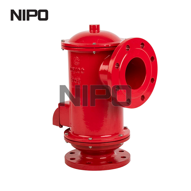
This design features a flanged connection on the outlet side. It directs vented gases into a vapor recovery unit, flare, or scrubber. It actively prevents atmospheric discharge. A pipe-away breather valve is mandatory for handling toxic, highly flammable, or valuable gases. Biogas, synthetic natural gas, and hydrogen blends fall into this category.
Routing the exhaust safely away from the tank protects both personnel and the environment. The closed-loop system ensures operators capture and process all fugitive emissions. Engineers must carefully calculate the backpressure generated by the downstream piping. Excessive backpressure can prevent the valve from opening at the correct set point, compromising tank safety. You must size the downstream header pipe larger than the valve outlet to minimize this backpressure.
Specialized variants use exotic alloys like Hastelloy, Monel, or Titanium. Many feature heavy PTFE linings to resist aggressive vapors. A pressure release breather valve for chemical industry tanks fits gas facilities co-located with chemical processing. It also handles highly corrosive trace elements found in raw energy streams.
Raw biogas often contains high levels of Hydrogen Sulfide. This compound rapidly degrades standard carbon steel or aluminum components. Upgrading the metallurgy ensures long-term operational safety and prevents sudden catastrophic structural failures. The robust construction withstands harsh chemical attacks, ensuring the internal pallets move freely without binding or corroding shut. You bolt the flange directly to the tank nozzle, knowing the wetted parts will survive the aggressive internal atmosphere.
Engineers must match valve specifications directly to system requirements. A mismatched valve compromises the entire storage network. Thorough technical evaluation prevents costly retrofits and dangerous operational failures. You must look beyond the basic flange size and evaluate the dynamic operating conditions.
Calculating maximum venting requirements is non-negotiable. You must account for thermal in-breathing and out-breathing driven by weather changes. Maximum pump rates also dictate the required flow capacity. The API 2000 standard provides the exact mathematical framework for these calculations, factoring in tank volume, insulation, and geographic latitude.
Undersizing leads directly to tank failure. The vessel will rupture or collapse if it cannot vent fast enough during a pump failure or sudden temperature drop. Oversizing causes valve chattering and accelerated wear. The pallet lifts, releases pressure instantly, and slams shut. This rapid cycling destroys the internal seals and damages the valve body. Precision sizing ensures smooth, stable operation during peak venting events.
API 2000 Sizing Variable | Operational Trigger | Impact on Valve Sizing |
|---|---|---|
Working In-Breathing | Maximum liquid pump-out rate | Determines required vacuum relief capacity |
Working Out-Breathing | Maximum liquid pump-in rate | Determines required pressure relief capacity |
Thermal In-Breathing | Sudden ambient temperature drop (e.g., rainstorm) | Adds massive vacuum demand to the total calculation |
Thermal Out-Breathing | Rapid ambient temperature rise (e.g., direct sunlight) | Adds pressure relief demand due to vapor expansion |
Gas composition directly impacts valve internals. Corrosive elements attack standard metals and harden rubber seals. You must select diaphragm materials based on temperature extremes and chemical exposure. A failed diaphragm allows continuous gas leakage and renders the set point inaccurate.
FEP handles extreme chemical exposure and resists sticky particulate buildup.
Nitrile works well for standard petroleum and dry gas applications at ambient temperatures.
Viton survives high temperatures and aggressive hydrocarbon blends.
EPDM provides excellent resistance to ozone and weather exposure.
Matching the elastomer to the specific gas ensures a reliable, bubble-tight seal over years of operation. Material degradation leads to immediate seal failure, allowing continuous gas leakage and pressure loss. Field technicians often discover hardened, cracked diaphragms during annual inspections when the wrong material was specified during procurement.
External factors heavily influence valve performance. Icing, freezing rain, and extreme ambient heat alter the set pressure. Ice buildup can freeze a pallet shut completely. This creates a highly dangerous over-pressure scenario where the tank cannot vent. A valve designed for a controlled indoor environment will fail rapidly when exposed to severe outdoor elements.
Harsh climates often require steam-jacketed valves or electric heat tracing to keep the internal components moving freely. Specialized weather hoods also protect the exhaust ports from snow, nesting birds, and wind-driven debris. You must evaluate the installation site climate before finalizing the specification. Adding a simple bird screen prevents insects and debris from fouling the precision-machined seating surfaces.
Balancing upfront specifications with long-term operational realities requires careful analysis. Every design choice carries a distinct mechanical trade-off. Engineers must prioritize features based on the specific risk profile of the gas facility.
Weight-loaded valves offer brilliant simplicity. They are easy to maintain and require no specialized tools for field calibration. However, they lack pinpoint precision near the opening threshold. Pilot-operated or magnetically-actuated valves provide highly precise pressure control. They maximize tank capacity by operating closer to the maximum allowable working pressure without leaking.
The trade-off involves maintenance complexity. These advanced mechanisms require specialized training, delicate handling, and strict maintenance schedules to function correctly. A facility lacking specialized technicians may struggle to maintain pilot-operated systems, making simpler weight-loaded designs a safer operational choice despite their lower precision. You must match the equipment complexity to the skill level of your on-site maintenance crew.
Standard allowable leak rates often sit around 1 SCFH at 90% of set pressure. Some low-risk applications tolerate this minor loss. High-value gas systems demand tighter tolerances. Investing in premium, tight-sealing valves prevents continuous product loss. The initial capital expenditure increases, but the operational savings justify the cost.
A standard pressure relief breather valve might leak slightly before reaching its full opening pressure. Upgrading to a high-performance magnetic or pilot-operated design stops these micro-leaks. The operational savings from retained gas and avoided environmental fines justify the upgrade. Facilities processing expensive synthetic gases must prioritize zero-leakage designs to protect their profit margins and maintain strict environmental compliance.
Installation and operation present common points of failure. Anticipating these risks prevents unplanned downtime and extends equipment life. Proactive engineering mitigates the most severe operational hazards before they cause a catastrophic failure.
Servicing the valve often requires venting or shutting down the entire tank. This disrupts the entire gas network and halts production. Integrating specialized isolation valves upstream solves this problem. Full-port ball valves or gate valves allow safe removal and inspection of the breather unit without taking the tank offline.
You can maintain the equipment without compromising the closed-loop system. Mechanical interlocking mechanisms ensure the isolation valve remains open during normal operation, preventing accidental tank isolation. Implementing strict lock-out/tag-out procedures further protects maintenance personnel from sudden gas releases during inspection. Never install a standard butterfly valve upstream, as the disc can interfere with the gas flow profile entering the breather unit.
Rapid open and close cycles destroy the valve seat. Oversized valves or improper inlet piping usually cause this chattering. The pressure drops too quickly upon opening, causing the pallet to slam shut. This mechanical hammering fractures internal components and shreds elastomer seals.
Strict adherence to sizing calculators prevents this issue. Ensure the inlet pressure drop does not exceed 3% of the set pressure. Proper pipe sizing stabilizes the gas flow and keeps the pallet open smoothly during venting events. Engineers must also avoid installing elbows or reducers immediately beneath the valve, as these fittings create flow turbulence that destabilizes the pallet. Always provide a straight run of pipe directly below the inlet flange.
Neglected valves fail to open. Sticky residues, polymer buildup, or corrosion fuse the pallet to the seat. This leads directly to catastrophic over-pressure. Establish routine testing intervals to verify performance. Relying on visual inspection alone is insufficient for critical safety devices.
Isolate the valve using the upstream full-port block valve.
Remove the valve from the tank nozzle and transport it to a clean testing environment.
Utilize specialized test benches to confirm the exact opening pressure and leak rates.
Inspect and replace the FEP or Nitrile diaphragms if any hardening or cracking is detected.
Clean the seating surfaces with approved solvents to remove sticky gas residues.
Reinstall the valve and document all test results to provide a verifiable safety record for regulatory compliance audits.
The optimal breather valve balances precise pressure management with absolute tank protection. It must withstand the specific chemical and environmental realities of the gas facility. Use pipe-away valves for hazardous or valuable gases. Specify chemical-grade valves for corrosive environments. Carefully select actuation types based on set-pressure requirements and maintenance capabilities.
Take the following steps to secure your gas distributed energy system:
Audit current tank design pressures and maximum allowable working pressures across all vessels.
Calculate required flow rates strictly following API 2000 guidelines for both thermal and pump-driven breathing.
Evaluate gas composition to finalize diaphragm and body material selection.
Consult with a specialized valve manufacturer for custom sizing and configuration.
Implement a rigid maintenance schedule utilizing upstream isolation valves for safe field testing.
A: A standard pressure release valve typically handles only over-pressure, often in liquid or high-pressure gas lines. A breather valve manages both low-pressure out-breathing and vacuum in-breathing for storage tanks. It actively balances the internal tank atmosphere with external conditions to prevent structural damage.
A: Pipe-away designs are mandatory when venting toxic, flammable, or environmentally regulated gases. Instead of releasing harmful vapors into the atmosphere, the flanged outlet routes the gas to a flare, scrubber, or vapor recovery system. This ensures strict environmental compliance and site safety.
A: The valve features a dedicated vacuum pallet mechanism. When internal pressure drops below atmospheric levels during rapid pump-out or sudden thermal cooling, the pallet lifts. This draws in ambient air or blanketing gas, equalizing the pressure and preventing the steel tank from imploding.
A: Corrosive environments require specialized metallurgy. Standard aluminum or carbon steel will degrade rapidly. Engineers must specify corrosion-resistant materials like 316L Stainless Steel, Hastelloy, or Monel. PTFE-coated internals and FEP diaphragms are also necessary to withstand aggressive chemical vapors and prevent sticking.
A: Chattering is usually caused by oversizing the valve for the actual flow rate or excessive pressure drop in the inlet piping. The pallet lifts, releases pressure too fast, and slams shut repeatedly. Prevention requires accurate API 2000 sizing and designing proper inlet piping to stabilize flow.
A: Industry standards typically advise annual inspections. However, highly corrosive, sticky, or particulate-heavy environments may require semi-annual checks. Installing upstream isolation valves facilitates this testing without shutting down the tank. Regular maintenance ensures the pallets lift freely at the correct set points.


