

close
Choose Your Site
Global
Social Media

Views: 0 Author: Site Editor Publish Time: 2026-08-20 Origin: Site


Misapplying pressure management valves in industrial storage and piping systems directly correlates to structural fatigue, catastrophic vessel failure, and severe environmental compliance violations. Engineering and facility teams must balance daily operational efficiency—such as vapor conservation and thermal equilibrium—with the necessity of emergency fail-safes against dangerous overpressure or vacuum events. Evaluating the exact mechanical differences, pressure thresholds, and compliance requirements dictates how you specify the correct valve architecture. We break down the technical distinctions between breather valves and pressure relief valves to support accurate, safety-compliant procurement decisions. You will learn how to match valve types to specific vessel ratings, operational demands, and environmental regulations without over-engineering the system.
Operational Intent: A breather valve manages routine, "physiological" pressure fluctuations caused by thermal changes and fluid transfer, whereas a pressure relief valve (PRV) acts as a unidirectional fail-safe for abnormal, "pathological" dangerous overpressure.
Pressure Thresholds: Breather valves operate at high-sensitivity, low-pressure ranges (typically measured in inches of water column, such as 0.5 to 2.5 INWC), while PRVs handle significantly higher setpoints (PSI or Bar).
System Protection: Atmospheric storage tanks rely on a pressure vacuum breather valve to prevent daily structural fatigue (implosion/rupture), while pressurized vessels require PRVs to prevent catastrophic explosions.
Compliance & Safety: Selecting the wrong valve compromises both API/OSHA safety standards and fugitive emission control protocols.
Maintaining atmospheric equilibrium inside a low-pressure storage tank requires continuous, bidirectional vapor management. A breather valve functions as the primary respiratory system for these vessels. During active filling operations, incoming liquid displaces the existing vapor space. If this vapor cannot escape, internal pressure rapidly escalates, risking roof rupture or seal degradation. Conversely, during liquid withdrawal or pump-out phases, the internal volume expands, creating a vacuum effect that can easily collapse a thin-walled atmospheric tank.
Beyond fluid transfer, ambient environmental factors dictate continuous valve actuation. Diurnal temperature cycles cause the vapor space to expand during the heat of the day (thermal out-breathing) and contract as temperatures drop at night (thermal in-breathing). A sudden rainstorm on a hot summer afternoon can cause rapid vapor contraction, pulling a severe vacuum in minutes. The valve utilizes highly calibrated, weight-loaded or spring-loaded pallets that lift precisely when the internal pressure or vacuum overcomes the setpoint. This bidirectional flow mechanism allows the inhalation of ambient air or a designated blanketing gas (like nitrogen) and the controlled exhalation of internal vapors, ensuring the vessel remains within its safe operating limits.
Industrial applications demand specific configurations based on the vessel's structural tolerances and the nature of the stored media. A standalone vacuum breather valve is engineered strictly to mitigate negative pressure. This configuration is deployed on tanks that are structurally capable of withstanding internal positive pressure but remain highly vulnerable to vacuum collapse. By focusing solely on inhalation, it provides a targeted defense mechanism during rapid pump-outs or sudden cooling events.
More commonly, facilities deploy a combined pressure vacuum breather valve. This dual-function device incorporates two distinct pallets within a single housing. One pallet governs the positive pressure relief, venting excess vapor to the atmosphere or a recovery header. The second pallet governs vacuum relief, opening inward to admit air or blanketing gas. This simultaneous management ensures comprehensive protection across all standard operational phases.
It is critical to distinguish these devices from air release valves. While air release valves are installed at high points in liquid piping networks to expel trapped air pockets and maintain fluid flow efficiency, they do not manage vapor space equilibrium. Breather valves are exclusively designed for the complex vapor dynamics of storage tanks, not liquid pipeline flow optimization.
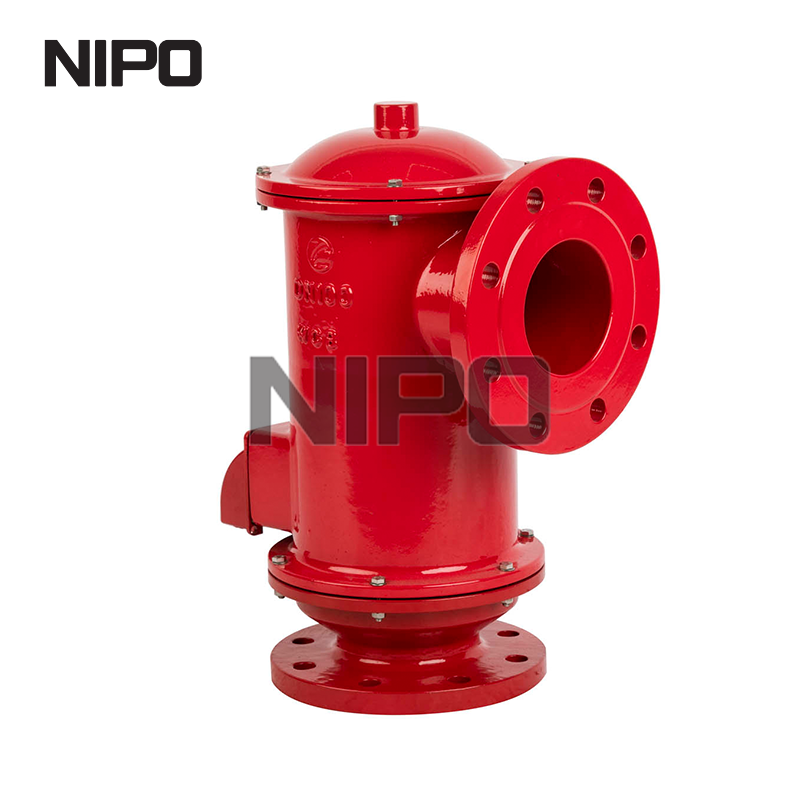
Unlike devices designed for daily operational breathing, a pressure relief valve (PRV) serves as a strict, unidirectional fail-safe. Its primary function is safety-critical venting during abnormal, pathological pressure spikes that threaten the structural integrity of a pressurized vessel or piping system. These fault conditions typically arise from severe external fire cases, blocked discharge outlets, thermal runaway reactions, or control valve failures.
When an emergency event causes internal pressure to surge rapidly, the PRV provides an immediate exhaust route. The flow design is strictly unidirectional; it vents media out of the system to reduce pressure but possesses no mechanism to inhale air or relieve a vacuum. Once the pressure drops back below the safe threshold—a point known as the blowdown pressure—the valve automatically reseats, sealing the system to prevent further loss of containment. The design philosophy here assumes the valve will remain closed 99% of the time, only actuating when process controls fail.
The mechanical response of a PRV is dictated by high-pressure thresholds that approach the vessel's Maximum Allowable Working Pressure (MAWP). Standard PRVs utilize a heavy-duty spring-loaded mechanism. The spring applies a constant downward force on a disc, keeping it firmly seated against the nozzle. When system pressure exerts an upward force that exceeds the spring's tension, the disc lifts, allowing rapid discharge.
For applications requiring tighter margins between normal operating pressure and the setpoint, pilot-operated relief valves are utilized. These valves use the system's own pressure, routed through a smaller pilot valve, to keep the main valve tightly closed until the exact setpoint is reached. This design prevents premature leakage and allows the system to operate much closer to its MAWP without risking accidental actuation. Regardless of the specific mechanism, PRV actuation is characterized by a rapid, high-capacity release designed to neutralize imminent explosive threats.
Technical Feature | Breather Valve | Pressure Relief Valve (PRV) |
|---|---|---|
Operating Pressure Range | Micro-fluctuations (0.5 to 2.5 INWC / Millibars) | High-pressure containment (15 PSI to thousands of PSI) |
Directionality of Flow | Bidirectional (Inhalation and Exhalation) | Unidirectional (Exhaust / Relief only) |
Primary Application | API 650 Atmospheric and low-pressure storage tanks | ASME Section VIII Pressurized vessels, boilers, reactors |
Operational Focus | Vapor conservation, emission reduction, daily equilibrium | Emergency fail-safe, catastrophic rupture prevention |
Actuation Frequency | Continuous, daily actuation based on thermal/pumping cycles | Rare actuation; remains closed unless a fault condition occurs |
The most defining distinction lies in the pressure ranges they govern. Breather valves are engineered for micro-fluctuations. Their setpoints are extremely low, typically measured in inches of water column (INWC) or millibars. A standard setting might range from 0.5 to 2.5 INWC, which translates to mere fractions of a PSI (1 INWC equals approximately 0.036 PSI). This extreme sensitivity requires lightweight pallets, precise machining, and specialized elastomer seals to ensure actuation at the slightest deviation from atmospheric equilibrium.
Conversely, PRVs are engineered for high-pressure containment. Their setpoints are measured in PSI or Bar, often ranging from 15 PSI up to several thousand PSI depending on the process. The internal springs and components are heavy and robust, designed to remain completely static until significant, dangerous force is applied against the seating area.
Fluid dynamics and flow direction separate the daily utility of these valves. Breather valves are inherently bidirectional. They must breathe in to relieve a vacuum and breathe out to relieve excess pressure. This dual-action capability is what maintains the delicate balance inside thin-walled tanks. If a tank is being emptied rapidly, the valve must pull in ambient air at a rate equal to the liquid discharge rate.
PRVs are strictly unidirectional. They are designed solely to exhaust media out of a pressurized system. They offer no protection against negative pressure or vacuum conditions, as their mechanical architecture only permits flow from the high-pressure internal environment to a lower-pressure exhaust header or the atmosphere.
The structural design of the protected vessel dictates the valve choice. Breather valves are the standard for fixed-roof atmospheric tanks, low-pressure storage tanks (typically operating below 15 psig), and vapor recovery systems. These vessels are constructed to hold large volumes of liquid but have very low tolerance for internal pressure variations. A standard API 650 tank can suffer roof deformation at just a few inches of water column overpressure.
PRVs are mandated for pressurized vessels built to ASME Section VIII standards, including boilers, chemical reactors, distillation columns, and high-pressure piping infrastructure. These robust systems require protection against massive pressure accumulations that low-pressure devices simply cannot handle.
While both valves contribute to overall facility safety, their primary operational focuses differ. Breather valves prioritize operational performance and daily system health. By remaining closed during normal conditions and opening only slightly during minor fluctuations, they minimize valuable product evaporation, prevent atmospheric moisture ingress, and reduce fugitive volatile organic compound (VOC) emissions. They are active participants in the daily process cycle.
PRVs are focused strictly on ultimate safety. They do not optimize daily performance or conserve vapor. They act as the absolute last line of defense against catastrophic rupture, prioritizing rapid, high-volume pressure relief over product conservation or emission reduction during an emergency.
The lifecycle and maintenance profiles of these valves are dictated by their actuation frequency. Breather valves experience continuous, daily actuation. Every time a transfer pump turns on, or the sun heats the tank shell, the valve pallets lift and seat. This constant movement requires regular inspection for wear, debris accumulation, and seating integrity.
PRVs experience rare actuation. In a properly functioning process system, a PRV may never open during its entire service life. It remains dormant, waiting for a fault condition. When it does actuate, it is considered a significant process safety event requiring immediate investigation into the root cause of the overpressure, followed by a mandatory inspection of the valve to ensure it reseated properly.
Specifying the correct pressure management device begins with a rigorous analysis of the vessel's structural limits. Atmospheric tanks designed to API 650 standards have specific design pressure and vacuum ratings that cannot be exceeded without risking permanent deformation. The valve setpoints must be calibrated to open well before the internal pressure reaches the tank's maximum design limits. You must calculate the exact flow rate required to keep the internal pressure below the failure point.
Vacuum protection requires particular attention. Thin-walled tanks are highly susceptible to implosion if the liquid withdrawal rate exceeds the air intake capacity. Specifying a highly calibrated vacuum relief valve for storage tank applications is a mandatory engineering requirement. The sizing calculations must account for the maximum possible pump-out rate, ensuring the valve orifice is large enough to admit ambient air rapidly enough to replace the displaced liquid volume. If a pump removes 1,000 gallons per minute, the valve must allow 1,000 gallons of air per minute to enter.
Regulatory compliance heavily influences valve selection and sizing. Engineering teams must navigate API 2000 standards, which dictate the venting requirements for atmospheric and low-pressure storage tanks. API 2000 provides complex formulas for calculating normal venting (due to liquid movement and thermal effects) and emergency venting (due to external fire exposure). You cannot guess these values; they must be mathematically proven based on the tank's physical dimensions and the stored media's flash point.
Simultaneously, environmental regulations mandate strict control over fugitive emissions. Facilities must meet EPA standards regarding the release of VOCs and hazardous air pollutants. This necessitates the selection of breather valves with advanced, tight-sealing pallets. Leakage rates must be rigorously tested, and valves often incorporate specialized elastomer diaphragms (like FEP or PTFE) to ensure a bubble-tight seal when the system pressure is below the setpoint, preventing continuous, low-level vapor leakage into the atmosphere.
The chemical composition of the stored media dictates the materials of construction for the valve housing and internal components. Standard carbon steel or aluminum may suffice for benign liquids, but aggressive chemical vapors require superior corrosion resistance. Engineers must select materials like 316 Stainless Steel, Hastelloy, or Monel for the valve body, while internal pallets and seats may require PTFE coatings to prevent chemical attack and degradation over time.
In facilities handling highly flammable or explosive media, standard venting is insufficient. The mandatory requirement for an explosion-proof pressure vacuum vent valve applies in ATEX-rated or hazardous locations. These specialized valves are often integrated with flame arrestors. If an external vapor cloud ignites, the flame arrestor matrix (typically a crimped metal ribbon design) quenches the flame front, preventing it from propagating through the valve and into the tank's vapor space, thereby averting a catastrophic internal explosion.
In the petrochemical and refining sectors, large-scale fixed-roof tanks store millions of gallons of crude oil, refined fuels, and chemical feedstocks. These tanks require continuous breathing to prevent roof fatigue. Without proper pressure vacuum management, the constant flexing of the roof plates during daily thermal cycles will eventually cause weld failure and structural degradation. Furthermore, in sour crude applications containing hydrogen sulfide (H2S), the breather valves must be piped to a closed vapor recovery system or flare header, requiring specialized pipe-away configurations rather than venting directly to the atmosphere. This protects site personnel from toxic gas exposure.
The transition to alternative fuels and decentralized power generation introduces new demands for pressure management. Biogas digesters, syngas storage, and hydrogen blending facilities operate under highly specific pressure regimes. Deploying a specialized pressure vacuum breather valve for gas distributed energy system applications ensures stable gas feed pressures to downstream turbines or compressors. These valves prevent system lockouts caused by pressure drops and manage the erratic volumetric fluctuations inherent in biological or synthetic gas production, ensuring continuous, safe energy generation.
A frequent operational failure in pressure management systems is valve chattering. This phenomenon occurs when a valve rapidly opens and closes in quick succession, causing the internal components to slam against the seat. The primary cause of chattering is improper sizing—specifically, utilizing an oversized valve for a low-flow application. When the oversized valve opens, it immediately vents the pressure, causing it to snap shut. The pressure quickly builds again, repeating the violent cycle. Overlapping setpoints between primary breather valves and secondary emergency relief devices can also induce erratic actuation.
Mitigation requires precise engineering at the procurement stage. Flow capacity calculations must strictly adhere to API 2000 guidelines, ensuring the valve orifice matches the actual vapor generation rates. Furthermore, engineers must stagger the set pressures of multiple relief devices. The primary breather valve should actuate first, with secondary emergency vents set at a higher threshold, ensuring smooth, sequential actuation only when required.
Environmental conditions and media characteristics pose severe risks to valve reliability. In cold climates, ambient moisture can condense and freeze on the valve pallets, locking them closed and rendering the tank vulnerable to overpressure or vacuum collapse. Similarly, certain chemical media, such as styrene or butadiene, are prone to polymerization. Vapors can condense and form solid, plastic-like deposits on the valve seats, cementing the pallets shut.
To mitigate freezing risks, facilities specify steam-jacketed or electrically traced valves that maintain internal temperatures above the freezing point of water or the condensation point of the vapor. To combat polymerization and sticking, internal components are treated with specialized non-stick coatings. Most importantly, establishing strict, condition-based maintenance schedules is mandatory to ensure these critical safety devices remain fully operable.
Field technicians must execute a rigorous inspection routine to prevent unexpected valve failures. We recommend the following baseline procedure every six months:
Isolate the valve from the active process line using block valves or by taking the tank out of service.
Remove the weather hood and inspect the protective screens for debris, ice buildup, or bird nests.
Manually lift the pallets to verify smooth, frictionless movement along the internal guide posts.
Inspect the elastomer seating diaphragms for chemical swelling, cracking, or polymerization buildup.
Clean the seating surfaces with an approved, non-abrasive solvent to remove sticky residues.
Reassemble the unit and perform a low-pressure bench test to verify the exact opening setpoint and confirm the leak rate meets EPA standards.
Conduct a thorough API 2000 sizing calculation to determine exact normal and emergency venting requirements based on liquid transfer rates and thermal exposure.
Review media compatibility to select appropriate housing materials and non-stick elastomer coatings that resist corrosion and polymerization.
Evaluate site-specific environmental compliance requirements to determine if pipe-away configurations or integrated flame arrestors are necessary for fugitive emission control.
Consult with a specialized valve engineer to finalize site-specific specifications and establish a rigorous, condition-based maintenance protocol.
A: No. A breather valve manages minor, low-pressure fluctuations (measured in inches of water column) for daily operational equilibrium. A pressure relief valve handles high-pressure emergency events (measured in PSI). Substituting one for the other will lead to catastrophic vessel failure or severe operational inefficiency.
A: Set pressures are highly specific to the tank's structural design, but they typically operate at very low thresholds, often ranging from 0.5 to 2.5 inches of water column (INWC) or approximately 2 to 22 millibars, ensuring actuation before the tank walls experience stress.
A: Atmospheric tanks primarily require breather valves for daily thermal and pumping variations. However, they also require emergency relief venting (often via an emergency pressure relief cover or hatch) to handle extreme overpressure scenarios like external fires, as dictated by API 2000.
A: Inspections should occur at least annually, though highly corrosive, polymerizing, or freezing environments require quarterly or monthly checks. Maintenance must verify pallet mobility, seat integrity, and ensure the integrated flame arrestor matrix is completely free of debris or blockages.
A: Leakage is typically caused by debris accumulation on the seating surface, degradation of the elastomer diaphragm due to chemical incompatibility, or mechanical wear from chronic valve chattering. Regular cleaning and specifying the correct seal materials prevent premature seating failures.
A: Air release valves are installed on liquid pipelines to expel trapped air pockets and optimize fluid flow. Breather valves are installed on storage tanks to manage vapor space equilibrium, inhaling and exhaling gases to prevent structural damage from pressure or vacuum buildup.


