

close
Choose Your Site
Global
Social Media

Views: 0 Author: Site Editor Publish Time: 2026-05-21 Origin: Site


Petrochemical facilities operate under intensely unforgiving conditions. Uncontrolled backflow leads directly to chemical cross-contamination, severe compressor damage, and critical safety hazards. Plant operators need highly reliable mechanical interventions to prevent these catastrophic events. The single disc check valve serves as a standard line of defense across numerous pipelines. However, its successful application requires precise alignment against complex fluid characteristics, tricky piping layouts, and rigid pressure constraints. Choosing an incorrect specification routinely causes system-wide disruptions.
We will provide a thorough technical evaluation framework. This guide helps you specify these crucial autonomous components accurately. You will learn how to evaluate operational mechanics, navigate strict industry compliance standards, and avoid dangerous installation pitfalls. By following this framework, engineering teams can ensure safer operations. They maximize system performance and maintain flawless process integrity throughout their facilities.
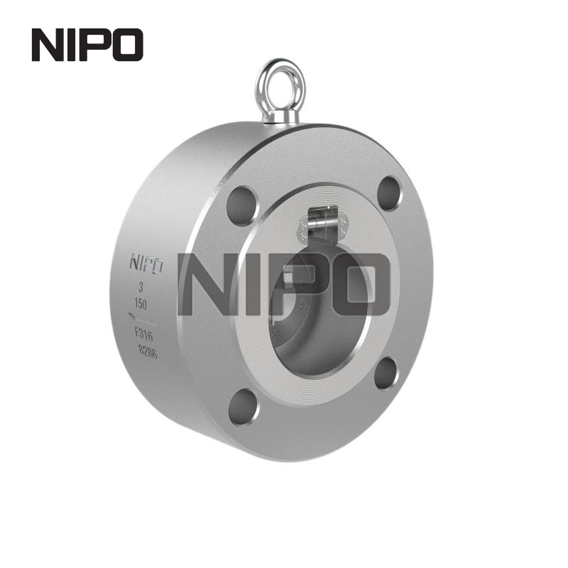
Single disc check valves offer high installation flexibility and structural simplicity, ideal for steady-flow, medium-pressure petrochemical applications.
Precise sizing based on expected head loss (Kv/Kvs values) and cracking pressure is required to avoid system inefficiency.
Compliance with industry standards (API 598, ASME B16.34, NACE MR0175) is non-negotiable for sour gas and corrosive hydrocarbon environments.
Improper installation orientation or ignoring soft-seal degradation are the primary failure vectors in petrochemical deployments.
Unplanned flow reversal creates massive pressure surges. These sudden surges easily destroy downstream pumps and fragile compressors. Centrifugal pumps spin backward when fluid reverses. This reverse rotation damages mechanical seals instantly. Bearings overheat and shatter under the unexpected directional load. You face weeks of downtime when major rotating equipment fails.
Process integrity faces equal danger. Petrochemical plants rely on exact chemical ratios. Backflow between mixed streams disrupts these delicate formulations. Contaminated fluid ruins entire production batches. Facilities then face severe regulatory incidents. Environmental compliance violations occur when toxic hydrocarbons escape containment. You must isolate streams effectively to prevent these scenarios.
A properly specified single disc check valve acts as your primary safeguard. It operates completely autonomously. The mechanism requires no external actuation or power source. It monitors flow momentum continuously. The device serves as a vital fail-safe against pressure anomalies. You can deploy it safely in unmanned zones. They provide constant protection inside hazardous environments where human intervention remains impossible.
Common Mistake: Relying on automated control valves to prevent backflow. Control valves have slow response times. They require power and signal integrity. A sudden power loss leaves the pipeline completely vulnerable to immediate backflow.
You must understand the internal mechanism to specify these units correctly. The device utilizes a hinged, swinging disc. A central pin suspends this disc inside the flow path. Forward fluid momentum pushes the disc open. The minimum upstream force required to initiate this opening is called the cracking pressure. The disc swings upward, clearing a path for the fluid.
When flow momentum drops, the disc responds immediately. Gravity and internal springs pull it downward. Reverse flow then applies pressure against the closed disc. This differential pressure forces the disc tightly against the seat. We call this specific sealing force the seating pressure. Higher reverse pressure creates a tighter, more secure seal.
Engineers often debate between single and dual-plate designs. Each mechanism presents distinct advantages.
The single disc features fewer moving parts. Fewer components mean easier in-line maintenance. It provides significantly higher installation flexibility. The open interior handles solid-bearing fluids exceptionally well. Dual-plate designs place a central hinge post directly in the flow path. This post catches catalyst fines and polymer debris. The single disc swings entirely out of the way. It prevents dangerous debris buildup.
However, this structural simplicity brings a slight trade-off. A single disc causes a slightly higher pressure drop than double disc alternatives. It rests partially in the flow path during normal operation. This creates minor head loss. Therefore, engineers prefer them for steady, highly stable flow environments.
Table 1: Single Disc vs. Double Disc Performance Comparison | ||
Evaluation Metric | Single Disc Valve | Double Disc Valve |
|---|---|---|
Solid Handling | Excellent. Free interior prevents debris snags. | Poor. Central post catches polymer strings. |
Moving Parts | Minimal (One hinge, one disc). | Complex (Two plates, central spring, dual hinges). |
Maintenance | Simple top-entry access. | Requires complete removal often. |
Head Loss | Moderate pressure drop. | Very low pressure drop. |
Ideal Flow State | Steady, stable velocity. | High-velocity, variable flow. |
Specifying pipeline hardware demands rigorous material and standard evaluation. Basic industrial valves fail quickly under petrochemical stress. You must align your selections against strict industry frameworks.
Standard PVC or commercial brass is completely insufficient here. Petrochemical applications demand robust alloys. You need 316 stainless steel, Hastelloy, or Inconel for reliable performance. Acidic streams erode basic carbon steel rapidly.
Many facilities process sour gas containing hydrogen sulfide (H2S). These environments induce sulfide stress cracking. Your specified hardware must meet NACE MR0175 / ISO 15156 standards. NACE certification ensures the metal resists sudden brittle failure. Non-compliant metals shatter under pressure, releasing lethal gases instantly.
You must evaluate maximum flow capacity carefully. The valve must remain fully open during normal operation. If flow velocity dips, the disc hovers partially closed. The disc bounces against the seat rapidly. We call this phenomenon "chatter". Chatter destroys hinge pins prematurely. It wears down the sealing surfaces within weeks.
Engineers calculate expected head loss using specific Kv or Kvs values. The Kv value represents the flow coefficient. It indicates how much fluid passes through at a specific pressure drop. Optimizing this value reduces pump strain. It improves overall system energy efficiency remarkably.
Procurement teams must demand proper documentation. Uncertified hardware introduces unacceptable facility risks. Ensure your manufacturers adhere to the following mandatory frameworks:
ASME B16.34: Governs precise pressure-temperature ratings. It dictates minimum wall thicknesses for safe operation.
API 6D: Outlines strict design parameters for heavy pipeline valves. It ensures structural integrity over decades.
API 598: Specifies rigorous valve inspection and testing procedures. It guarantees bubble-tight shut-off capabilities before shipment.
ISO 15848: Mandates strict fugitive emission testing. It ensures stem and bonnet seals prevent greenhouse gas leakage.
Best Practice: Always request the API 598 testing logs from your manufacturer before authorizing delivery. Do not accept internal factory certificates as substitutes for official API testing.
Even perfectly designed hardware fails if installed improperly. Petrochemical environments magnify small installation errors. You must address orientation and hydraulic dynamics before bolting flanges.
A single disc check valve provides excellent versatility. However, vertical installations demand careful mechanical planning. Installing them in a vertical line with upward flow works perfectly. Gravity assists the closure mechanism naturally.
Downward flow presents a severe challenge. Gravity pulls the internal disc open. Fluid flow also pushes it open. You must specify heavily tensioned springs to counteract gravity. Without specific spring-tension modifications, the disc misaligns. The valve fails to close before fluid reverses. Engineers should generally avoid downward vertical installations unless absolutely necessary.
High-velocity liquid lines introduce severe hydraulic shock risks. Fluid momentum carries massive kinetic energy. If the disc closes too rapidly, the fluid stops instantly. This creates a violent pressure spike known as water hammer. The resulting shockwave travels backward through the pipe. It shatters pipe supports and fractures pump casings.
You must assess the need for hydraulic dampeners. Certain single disc valves feature external dashpots. These mechanical dampeners slow the final degrees of closure. They bleed off the kinetic energy safely. If dampeners remain unfeasible, evaluate non-slam nozzle variants instead.
Proactive maintenance prevents catastrophic blowouts. Operators must train to spot early warning signs. Identifying subtle symptoms saves millions in unplanned downtime.
Localized Condensation: Inspect the exterior bonnet joints. Unexplained wetness indicates early O-ring failure. Soft seals degrade over time.
Inconsistent Pressure: Monitor your downstream gauges. Fluctuating pressure indicates partial seating. Debris buildup on the hinge prevents full closure.
Audible Clicking: Listen near the installation site. Rhythmic clicking indicates disc chatter. The flow velocity is too low to keep the valve fully open.
Smart procurement requires looking beyond basic dimensions. You must evaluate long-term maintenance needs and operational efficiency. The initial purchase price represents a tiny fraction of the equipment's true operational impact. You should evaluate long-term energy efficiency closely. Calculate the energy required to overcome the valve's internal pressure drop. Highly efficient valves reduce pump workload significantly.
Soft seals act as regular consumables in petrochemical plants. Elastomers like Viton or PTFE degrade under harsh chemical exposure. Shortlist vendors offering readily available OEM replacement kits. You should prioritize designs allowing easy top-entry inspection. Top-entry models let technicians replace internal parts quickly. They do not require full removal from the active pipeline. This feature reduces maintenance turnarounds from days to mere hours.
Engineers must follow logical decision pathways. The following chart summarizes the optimal shortlisting logic.
Chart: Decision Matrix for Valve Selection | ||
Application Scenario | Recommended Valve Strategy | Primary Justification |
|---|---|---|
Medium flow velocities, stable pipeline. | Proceed with Single Disc | Minimal chatter risk. High reliability. |
Fluids containing catalyst solids. | Proceed with Single Disc | Open flow path prevents debris trapping. |
Severe space constraints in pipe rack. | Pivot to Wafer/Double Plate | Compact face-to-face dimensions save space. |
Extreme high-velocity liquid lines. | Pivot to Axial Flow / Non-Slam | Mandatory requirement to mitigate water hammer. |
Always verify your pipeline data against this logic. Match the hardware precisely to your specific fluid velocity profiles. Do not guess your operational parameters. Accurate data drives successful mechanical deployments.
Specifying a single disc check valve requires intense technical diligence. You must look far past basic pipe diameters and flange dimensions. Engineers must analyze material standard compliance, pipeline flow stability, and specific orientation limits. An overlooked vertical installation parameter easily causes immediate system failure. A forgotten NACE certification risks catastrophic environmental releases.
Take proactive next steps today. Engineers should audit all current facility flow data. Document exact maximum velocities, pressure spikes, and fluid corrosivity levels. Contact your shortlisted manufacturers immediately. Request specific Kv performance curves and official API testing logs prior to procurement. By strictly aligning your specifications with verified data, you guarantee long-term petrochemical safety.
A: Cracking pressure is the absolute minimum upstream pressure required to push the disc open and initiate forward flow. Seating pressure is the reverse differential pressure required to seal the disc completely against backflow. Low cracking pressure saves energy, while high seating pressure guarantees a tight, leak-proof seal during emergencies.
A: Yes, it works perfectly for upward fluid flow. Gravity assists the disc in closing naturally. However, for downward flow installations, gravity interferes with the closing mechanism. You must use specially tensioned springs to overcome gravity, or select a different valve style entirely to ensure reliable sealing.
A: Inspection frequency depends heavily on the chemical medium. However, operators should conduct proactive visual inspections for external weeping or condensation monthly. Full diagnostic checks, including pressure testing and soft-seal evaluations, should be scheduled during standard plant turnarounds. These major inspections typically occur every 2 to 5 years.


