

close
Choose Your Site
Global
Social Media

Views: 0 Author: Site Editor Publish Time: 2026-07-09 Origin: Site


In industrial fluid management, the integrity of system isolation relies entirely on the correct specification of shut-off mechanisms. A gate valve serves as the primary barrier to permit or prevent the flow of liquids and gases, providing a tight seal and an unobstructed path when fully open. Specifying the wrong valve type or failing to align valve metallurgy, bonnet design, and trim selection with system parameters leads to catastrophic leaks, premature seat wear, and costly unplanned downtime. Field engineers frequently encounter failures caused by misapplication, particularly when isolation valves are improperly subjected to throttling conditions.
Moving beyond basic definitions, this guide provides a technical evaluation framework for engineering and procurement teams to determine exact applications, assess industry standards, and mitigate operational risks. We will examine the mechanical variations, material requirements, and compliance mandates that dictate successful valve deployment across heavy industries.
Strict Isolation Functionality: Gate valves are engineered exclusively for fully open or fully closed operations; utilizing them for flow throttling guarantees accelerated wear and system inefficiency.
Application-Specific Metallurgy: Media characteristics dictate material choice, making configurations like the stainless steel gate valve API 600 standard non-negotiable for corrosive or high-pressure petrochemical environments.
Standardization Drives Reliability: Compliance with API, ASME, and AWWA standards ensures predictable performance and lifecycle cost management.
Vendor Vetting is Critical: Partnering with an established gate valve manufacturer with transparent QA/QC and testing protocols (e.g., API 598) is essential for mitigating supply chain and compliance risks.
Engineers specify these valves when a straight-line flow of fluid and minimum restriction is required. When the valve is fully open, the gate is completely drawn up into the valve bonnet. This leaves an unobstructed flow path through the valve, resulting in a minimal pressure drop across the system. High flow efficiency makes this design the preferred choice for large-diameter pipelines where maintaining fluid velocity and reducing pump energy consumption are critical operational metrics.
Fluid dynamics dictate a strict prohibition against throttling. Partially open gates suffer from intense vibration as the high-velocity fluid strikes the wedge. This turbulence causes cavitation, rapid seat degradation, and wire drawing on the sealing surfaces. The mechanism is strictly designed for on/off isolation. When operators attempt to regulate flow with these devices, the localized velocity increase across the partially open wedge strips away the seating material, destroying the valve's ability to provide a drop-tight seal when eventually closed.
It is important to distinguish between a standard wedge design and a knife gate variant. A standard wedge is utilized for clean or high-pressure fluids, relying on the wedging action to create a tight seal against the valve body. Conversely, a knife gate valve is engineered with a sharp edge to physically cut through thick slurries, pulp, and wastewater solids that would otherwise jam a standard wedge. Knife gates typically feature a thinner profile and are often unidirectional, making them highly specialized for bulk material handling and heavy effluent lines.
Actuation mechanics vary based on operational requirements and physical accessibility. Multi-turn manual handwheels are standard for accessible locations where operation is infrequent. For automated systems, remote locations, or exceptionally large valves requiring significant torque, engineers integrate pneumatic, hydraulic, or electric actuators. Gear operators are frequently installed on larger manual valves to reduce the rim pull required by operators, ensuring the valve can be seated and unseated safely against high differential pressures.
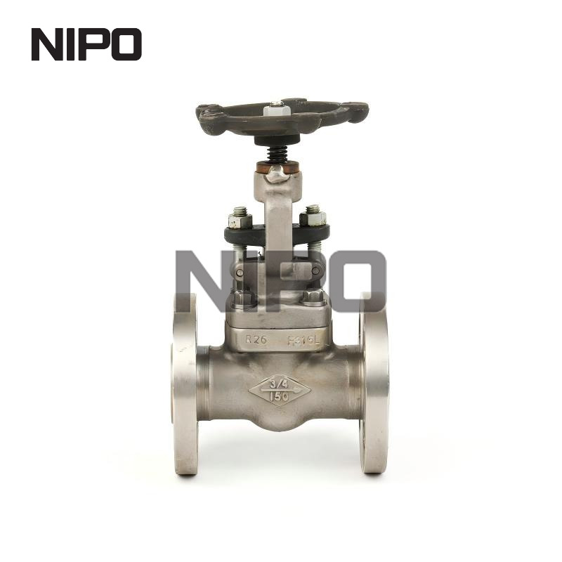
Municipal water supply networks, wastewater treatment facilities, and desalination plants rely heavily on robust isolation valves. Specifying gate valves for water treatment requires configurations that handle high volumes of fluid with minimal pressure loss. Resilient-seated designs are heavily preferred in these applications. The elastomer coating on the wedge encapsulates suspended solids, ensuring a drop-tight seal without damaging the metal seating surfaces. Compliance with AWWA C509/C515 standards is mandatory to guarantee potable water safety and long-term corrosion resistance in subterranean installations. Field crews often install these with non-rising stems and square operating nuts for access via T-keys from street level.
The hydrocarbon sector demands absolute reliability for pipeline isolation, refinery operations, and tank farm management. Robust isolation prevents cross-contamination and ensures safety during maintenance. The straight-line flow characteristic is mandatory when handling viscous fluids such as crude oil and heavy slurries. Any internal obstruction would cause unacceptable pressure drops and potential blockages within the pipeline infrastructure. Furthermore, pipeline pigging operations require full-bore valves to allow cleaning and inspection tools to pass through the piping network without obstruction.
Power plants utilize these valves in steam generation, superheaters, and boiler systems. Extreme temperatures introduce severe thermal expansion challenges. Specific wedge designs, such as flexible or split wedges, are required to prevent the valve from binding shut as the metal expands and contracts during thermal cycling. High-pressure steam applications also necessitate advanced bonnet designs, such as pressure seal bonnets, which utilize the internal system pressure to reinforce the bonnet gasket seal, preventing dangerous steam leaks in the plant environment.
The internal wedge dictates how the valve handles temperature fluctuations and physical stress. Selecting the wrong wedge type for a high-temperature application is a common cause of operational failure.
Solid Wedge: Best for general use. It offers high strength and simplicity but is highly susceptible to thermal binding in high-temperature services. If a solid wedge is closed while the system is hot, the subsequent cooling and contraction of the valve body can lock the wedge in place.
Flexible Wedge: Designed with a cut around the perimeter, it compensates for seat distortion and thermal expansion, making it ideal for fluctuating temperatures. This flexibility allows the wedge to adapt to slight deformations in the valve body caused by piping loads.
Split Wedge / Parallel Disk: Features self-aligning seating surfaces. This design is optimal for preventing binding in high-temperature steam applications. The two-piece construction allows the disks to move independently, ensuring a tight seal even if the valve body distorts.
Stem configuration impacts maintenance, environmental protection, and space requirements in the piping gallery.
Evaluate the vertical clearance above the valve installation point to determine if a rising stem can be accommodated.
Assess the corrosivity of the internal media to decide if the stem threads must be isolated from the fluid.
Determine the necessity for visual position indication for safety and operational monitoring.
Review the maintenance schedule to ensure adequate access for lubricating exposed stem threads.
Rising Stem (OS&Y - Outside Screw and Yoke) designs ensure the stem rises as the valve opens, providing immediate visual indication of the valve position. This is required for critical isolation where external thread lubrication is necessary and the threads must be kept out of the process media. Non-Rising Stem designs feature a stem that rotates but does not lift. This provides a compact footprint for underground or space-restricted installations, though the stem threads remain exposed to the internal media, making them unsuitable for corrosive or particulate-heavy fluids.
The bonnet secures the internal components and maintains pressure integrity. The choice of bonnet directly correlates with the system's pressure class and maintenance frequency.
Bonnet Type | Characteristics | Best Application |
|---|---|---|
Screwed Bonnet | Simplest design, threaded directly to the body. | Low-pressure, low-cost applications where frequent maintenance is not expected. |
Bolted Bonnet (BB) | Robust joint sealing using bolts and a gasket. | High-pressure industrial applications requiring regular internal maintenance and inspection. |
Welded Bonnet (WB) | Eliminates body-to-bonnet leak paths entirely. | High-pressure steam applications where internal maintenance is infrequent and leak prevention is paramount. |
Pressure Seal Bonnet (PSB) | Utilizes system pressure to mechanically tighten the internal seal. | Extreme high-pressure, high-temperature steam systems typically above Class 900. |
End connections must match the piping system design. Flanged ends allow for easy removal and maintenance, threaded (NPT) connections suit smaller pipes in utility services, and butt-weld or socket-weld connections provide permanent, leak-proof joints for high-pressure mandates. Material selection is dictated by media compatibility and environmental conditions. Cast iron or ductile iron is standard for water and low-pressure systems. Carbon steel is specified for high-pressure environments, while exotic alloys and stainless steel are required for highly corrosive media or cryogenic applications.
The American Petroleum Institute (API) 600 specification governs steel gate valves with flanged and butt-welding ends. Specifying a stainless steel sate valve API 600 standard provides the benchmark for heavy-wall thickness, corrosion allowance, and robust stem-to-wedge connections required in the severe conditions of the hydrocarbon industry. This standard ensures the valve body can withstand significant piping loads and pressure surges without compromising the internal seal. API 600 valves are characterized by their rugged construction, making them the default choice for refineries and chemical processing plants.
The internal wetted parts, including the stem, seating surfaces, and wedge seating faces, are referred to as the trim. The API 600 Trim Chart defines the exact materials used for these critical components. Matching trim materials to the process media prevents galling and corrosion on the sealing surfaces, directly extending operational life.
Trim Number | Material Composition | Typical Application |
|---|---|---|
Trim 5 | Stellite facing on seats and wedge | High temperature, severe service, excellent wear resistance. |
Trim 8 | 13% Cr (F6a) stem and seating surfaces | General oil and gas service, moderate corrosion resistance. |
Trim 12 | 316 Stainless Steel with Stellite facing | Corrosive environments requiring high durability and galling resistance. |
Other critical standards include ASME B16.34, which dictates pressure-temperature ratings and minimum wall thickness based on the chosen material. API 598 sets the strict parameters for valve inspection, testing, and acceptable leakage tolerances during hydrostatic and pneumatic pressure tests. AWWA C509/C515 governs valves used specifically in municipal waterworks, ensuring resilient seated designs meet strict durability and hygiene requirements.
Thermal binding occurs when a valve is closed while hot; as the system cools, the valve body contracts around the wedge, jamming it shut. This requires immense force to open, often damaging the stem or actuator. Pressure locking happens when high-pressure fluid becomes trapped in the bonnet cavity and expands due to ambient heat. Mitigation strategies include installing external bypass lines to equalize pressure or drilling equalization holes in the upstream side of the wedge to vent trapped pressure back into the process line.
Lifecycle maintenance requires managing slow actuation times inherent to multi-turn designs. Routine maintenance involves repacking stem glands to prevent fugitive emissions and repairing seating surfaces damaged by debris or improper throttling. Field technicians must regularly inspect the yoke sleeve and stem threads on OS&Y valves, applying appropriate industrial lubricants to prevent thread galling and ensure smooth operation during emergency shutdowns.
Large-diameter OS&Y valves are exceptionally heavy and require significant vertical clearance. Engineering teams must evaluate the structural support required in piping galleries and ensure adequate space for the stem to fully extend during operation. Inadequate pipe supports near heavy valves can lead to flange misalignment, inducing stress on the valve body and causing premature gasket failure.
Partnering with a reliable gate valve manufacturer ensures system integrity and compliance across complex industrial projects.
Engineering and Customization Capabilities: Assess the vendor's ability to modify trim materials, integrate specific actuation mounts, and alter end connections for bespoke applications. A capable manufacturer will offer in-house engineering support to verify flow calculations and material compatibility.
Testing and Quality Assurance: Demand absolute transparency. Require hydrostatic and pneumatic testing documentation, Material Test Reports (MTRs), API 598 compliance records, and fugitive emissions testing results (such as API 624 or ISO 15848-1). Verify that the facility maintains rigorous traceability for all pressure-retaining castings.
Supply Chain and Aftermarket Support: Evaluate manufacturing lead times. Confirm the immediate availability of replacement parts like gaskets, packings, and wedges. Strong field service capabilities are essential to minimize operational downtime during turnaround events and emergency maintenance scenarios.
Gate valves remain the fundamental standard for reliable, low-pressure-drop isolation across industrial sectors, provided they are strictly utilized for on/off applications. Proper specification prevents premature failure and ensures system safety.
Audit current Piping and Instrumentation Diagrams (P&ID) to verify that all installed isolation valves are used exclusively for on/off service, not throttling.
Define exact material and trim requirements based on media corrosivity, operating pressure, and maximum temperature limits before issuing purchase orders.
Request comprehensive technical data sheets, cross-sectional drawings, and material test reports from shortlisted manufacturing partners.
Implement routine field inspection schedules focusing on stem packing integrity, thread lubrication, and actuator responsiveness.
A: No. They are designed strictly for fully open or fully closed isolation. Using them for throttling causes the high-velocity fluid to vibrate the wedge, leading to cavitation, severe seat damage, and eventual sealing failure.
A: A standard wedge design seals by wedging metal against metal or elastomer, ideal for clean fluids. A knife gate features a sharpened disc designed to physically slice through thick slurries, pulp, and solid-heavy wastewater.
A: API 600 mandates heavy wall thicknesses, specific corrosion allowances, and robust stem-to-wedge connections. This ensures the valve can withstand the extreme pressures, temperatures, and corrosive environments typical in the petrochemical industry.
A: Trim numbers designate the specific materials used for the internal wetted parts (stem, seats, wedge faces). Selecting the correct trim prevents galling, resists media-specific corrosion, and ensures a durable seal over the valve's lifespan.
A: These issues are mitigated during the design phase by utilizing flexible or split wedges, installing external bypass lines, or drilling a small equalization hole on the upstream side of the wedge to relieve trapped bonnet pressure.
A: A rising stem (OS&Y) lifts out of the valve, providing a clear visual indication of whether the valve is open or closed. A non-rising stem rotates in place, saving vertical space but offering no visual position indicator.


