

close
Choose Your Site
Global
Social Media

Views: 0 Author: Site Editor Publish Time: 2026-10-20 Origin: Site


A flame arrestor only works if you install it correctly. Incorrect placement allows a deflagration to transition into a catastrophic detonation, rendering the safety device completely useless. Engineering and procurement teams often face a severe disconnect in the field. They purchase the correct specification but fail to execute a compliant installation. Field execution must account for piping geometry, flow direction, and environmental variables. A poorly installed unit provides a false sense of security and puts the entire plant at risk. This guide provides a rigorous, step-by-step framework for field installation. We detail pre-installation verification, critical positioning rules, and long-term maintenance considerations. You will learn how to ensure regulatory compliance and protect facility infrastructure from catastrophic fire propagation.
Location is Critical: In-line flame arrestors must be installed within the manufacturer-specified maximum distance (L/D ratio) from potential ignition sources to prevent flame acceleration.
Orientation and Flow: Strict adherence to the designated flow direction (uni-directional vs. bi-directional) and physical orientation (vertical vs. horizontal) is mandatory for the element to quench flames effectively.
Piping Geometry Matters: Bends, valves, and changes in pipe diameter between the ignition source and the arrestor alter flame speed and must be accounted for in the system design.
Maintenance Accessibility: Installation must incorporate structural support and adequate clearance to allow for routine inspection and cleaning of the flame cell without dismantling the entire pipeline.
A successful installation begins long before wrenches hit the flanges. Field teams must verify that the delivered unit matches the exact process conditions evaluated during the procurement phase. This includes checking the gas or fuel group, operating pressure, and maximum operating temperature. You must cross-reference the equipment nameplate against applicable executive standards like ISO 16852, API 2000, or NFPA 69. Installing a unit certified for Gas Group IIA into a process handling Gas Group IIC will result in immediate failure during an ignition event. The Maximum Experimental Safe Gap (MESG) of the element must align perfectly with the process fluid.
You must confirm whether the unit is rated for deflagration or detonation. Deflagrations involve subsonic flame speeds. Detonations involve supersonic flame speeds accompanied by massive shockwaves. This distinction dictates the permissible installation location. Deflagration arrestors have strict distance limits from the ignition source. Detonation arrestors are built to withstand severe kinetic impacts and offer more flexible placement. Installing a deflagration unit where a detonation could occur guarantees catastrophic structural failure of the housing.
Visual inspection of the internal structure is mandatory before bolting the unit into the pipeline. Installation teams must examine the crimped ribbon or flame cell element. Look for shipping damage, crushed channels, or misalignments. Even a microscopic deformation in the crimped ribbon alters the quenching gap. This allows flames to pass through. Shine a strong flashlight through the element to ensure no packing materials, dirt, or debris block the flow paths. Blockages increase pressure drop and create localized hot spots during normal operation.
Material verification ensures long-term operational integrity. You must verify both the housing and the element materials against the process fluid's chemical composition. Highly corrosive environments, offshore platforms, or processes handling aggressive vapors demand specific metallurgy. In these cases, installing a stainless steel flame arrestor is required to prevent rapid degradation of the quenching gaps. Specialized industries have even stricter requirements. Food, beverage, or pharmaceutical applications dictate specific surface finishes and cleanability standards. Initiating a sanitary flame arrestor specification inquiry early in the design phase is critical. This ensures the unit arrives with the correct Tri-Clamp connections and electropolished surfaces required for hygienic installation.
Before moving the unit to the installation site, perform a comprehensive bench check. This involves several specific steps to guarantee the unit is ready for field deployment. Skipping these checks often leads to rework and extended downtime during the commissioning phase.
Verify the nameplate data against the piping and instrumentation diagram (P&ID).
Inspect the flange faces for scratches, gouges, or rust that could prevent a proper seal.
Measure the internal diameter of the adjacent piping to ensure it matches the arrestor's bore exactly.
Check the torque markings on the factory-assembled housing bolts to confirm they have not loosened during transit.
Remove any temporary shipping covers only when the unit is ready to be lifted into place.
The Run-Up Distance, expressed as the L/D (Pipe Length to Pipe Diameter) ratio, is the most critical installation parameter. This ratio defines the maximum allowable distance from the potential ignition source to the arrestor face. To calculate this, divide the straight pipe length (L) by the internal pipe diameter (D). Manufacturers test and certify deflagration arrestors to specific maximum L/D ratios. Exceeding this distance allows the flame front to accelerate. The flame speed and pressure will exceed the device's quenching capability. If your unit has a certified L/D of 50 on a 2-inch pipe, the absolute maximum installation distance from the ignition source is 100 inches.
Direction of flow and physical orientation require strict adherence to manufacturer markings. You must identify flow direction indicators stamped or cast onto the equipment housing. For uni-directional models, gas or liquid flow must pass strictly from front to back. Installing a uni-directional unit backward compromises its structural ability to absorb the flame's kinetic impact. Bi-directional units can handle ignition from either side, but orientation still matters. Evaluate the implementation realities of vertical versus horizontal installation. Horizontal installations can trap condensate or particulates against the element face. If horizontal placement is unavoidable, eccentric reducers with flat bottoms should be used to facilitate drainage. Vertical installations generally allow better liquid drainage but require careful consideration of pipe support.
Managing piping geometry between the ignition source and the arrestor is highly regulated. Pipe bends, elbows, tees, and cross-sectional area changes act as turbulence generators. Turbulence accelerates flame propagation, rapidly turning a deflagration into a detonation. Guidelines typically require a specific length of straight, unobstructed pipe run before and after the arrestor. ISO 16852 dictates strict rules on pipe expansions or contractions. Never install a pipe diameter reduction immediately before the arrestor on the unprotected side. This acts as a nozzle, jetting the flame into the element at speeds far exceeding its certified limits.
Understanding the physics of flame propagation helps field teams appreciate these strict rules. When a gas mixture ignites in a pipe, the flame front expands. This expansion pushes unburned gas ahead of it, compressing it. This compression is known as pressure piling. As the unburned gas compresses, its temperature rises, and the flame front accelerates. If the pipe has bends or valves, the gas flow becomes turbulent. Turbulence increases the surface area of the flame front, causing it to consume the unburned gas even faster. This rapid acceleration is why the L/D ratio and straight pipe requirements are absolute limits, not mere suggestions.
Parameter | Deflagration Arrestor | Stable Detonation Arrestor | Unstable Detonation Arrestor |
|---|---|---|---|
Flame Speed | Subsonic (slower than sound) | Supersonic (constant velocity) | Supersonic (accelerating/shockwave) |
L/D Ratio Limit | Strictly limited (e.g., L/D < 50) | Flexible (can be installed further away) | No restriction on distance |
Piping Geometry Restrictions | No bends/valves between ignition and unit | Can tolerate minor turbulence generators | Designed for severe turbulence and bends |
Housing Strength | Standard pressure containment | Heavy-duty construction | Maximum structural reinforcement |
Typical Application | Short vent lines, near ignition sources | Long straight pipelines | Complex piping networks with multiple bends |
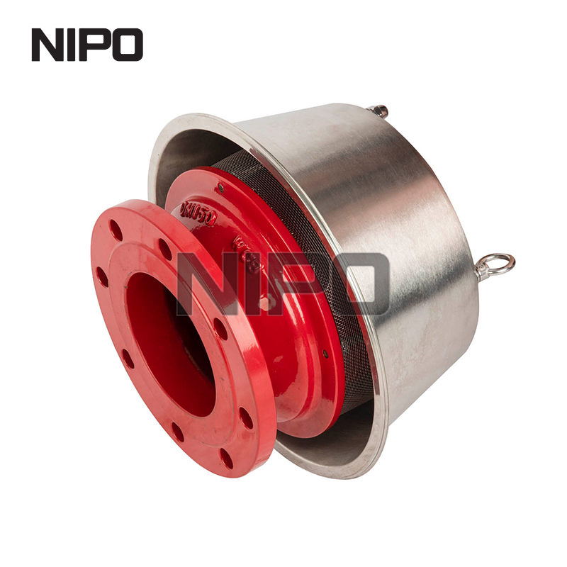
Installation requirements differ drastically between end-of-line (vent-line) and in-line configurations. End-of-line arrestors are designed to keep an external flame out of a tank or vessel. They vent directly to the atmosphere. Installation must account for weather protection. Hoods or cowls must be fitted to prevent rain, snow, or debris from blocking the flame cell. You must maintain specific open pipe end clearances to ensure unhindered vapor dispersion. In-line arrestors are designed to ensure a flame burning within a closed pipeline does not propagate further into the system. They require flanged connections on both sides and strict adherence to the L/D ratio calculations discussed earlier.
Bulk hydrocarbon storage presents unique hazards. Installing a flame arrestor for oil depot storage requires integrating the unit with pressure/vacuum relief valves (PVRVs) on tank roofs. The arrestor is typically installed immediately below the PVRV. This configuration protects the tank from atmospheric ignition sources, such as lightning strikes igniting vented vapors. Vapor recovery unit (VRU) pipeline installations face different challenges. These lines handle continuous vapor flow. The installation must account for potential particulate buildup and ensure the unit does not create an excessive pressure drop that disrupts the VRU compressor's efficiency.
Burner Management Systems (BMS) and process lines require precise installation protocols. Fuel gas lines feeding industrial burners must use arrestors compatible with the specific fuel group. Proximity to burner valves is critical. The unit must be installed close enough to the burner to catch a flashback immediately. Furthermore, the installation must integrate with automated safety shut-off systems. If a flashback occurs, sensors must detect the event and instantly trigger the BMS to isolate the fuel supply, preventing a continuous burning scenario on the element face.
Flare systems represent another highly specialized application. Flare lines collect waste gases from across a facility and direct them to a flare stack for safe combustion. These lines are often large in diameter and span long distances. Detonation arrestors are almost always required in flare headers because the long pipe runs allow deflagrations to easily transition into detonations. Installing these massive units requires heavy lifting equipment and extensive structural engineering. The piping must be designed to handle the immense thrust forces generated if a detonation shockwave hits the arrestor housing.
Structural support and pipe stress pose significant risks to the integrity of the housing. These devices are often heavy, especially detonation models with thick flanges and massive flame cells. Relying on the adjacent piping to support this weight causes pipeline stress. This stress can deform the housing, altering the internal gaps of the flame cell and rendering it unsafe. Mitigation requires independent support structures engineered specifically for the arrestor's weight. Proper use of expansion joints isolates the unit from thermal expansion forces in long pipe runs. Field teams must strictly follow torque specifications and tightening sequences for flange bolting to prevent uneven stress on the housing body.
Thermal monitoring is essential to mitigate the risk of short-time burning. A stabilized flame can anchor itself on the element face if the gas flow continues after an ignition event. No flame cell can withstand continuous burning indefinitely; the heat will eventually conduct through the metal and ignite the process fluid on the protected side. Installation must include temperature sensors, typically PT100 RTDs, tapped directly into the housing on the unprotected side. These sensors detect the rapid temperature rise associated with a stabilized flame. The sensors must be wired to the facility's control system to trigger automated process shutdowns and isolate fuel flow within minutes of detection.
Environmental and operational hazards require proactive installation planning. External factors like ice formation, bird nesting, and airborne debris can completely block end-of-line units. Weather hoods and coarse bird screens provide baseline protection. For processes prone to freezing, heat tracing or insulation might seem necessary. However, you must evaluate the trade-offs. Applying heavy insulation can compromise the arrestor's ability to dissipate heat during a deflagration. If heat tracing is used, it must be carefully engineered to maintain vapor temperature without acting as a thermal blanket that traps catastrophic heat during a fire event.
Vibration is an often-overlooked implementation risk. Compressors, pumps, and high-velocity gas flows generate continuous vibration in the piping system. Over time, this vibration can cause the crimped ribbon element to loosen or shift within its housing. A loose element creates larger gaps, destroying the unit's quenching ability. To mitigate this, piping systems must incorporate vibration dampeners. Additionally, the arrestor should be installed as far away from heavy vibration sources as the L/D ratio allows. Regular visual inspections must include checking the element for any signs of mechanical wear or shifting caused by systemic vibration.
Flame arrestors require periodic cleaning to prevent pressure drop increases and maintain quenching efficiency. Designing for element removal is a mandatory phase of installation planning. You cannot weld these units permanently into a rigid pipeline. The piping layout must use flanged spool pieces or eccentric reducers to allow safe, ergonomic removal of the flame cell. Maintenance personnel must be able to slide the heavy element out for inspection without utilizing heavy rigging equipment or cutting pipe. Providing adequate physical clearance around the installation site ensures maintenance teams can perform their tasks safely during routine plant turnarounds.
Post-installation documentation and compliance verification finalize the process. Commissioning checks must be rigorous. Inspectors must verify flange alignment to ensure zero stress is transferred to the housing. They must confirm sensor integration, testing the PT100 loops back to the main control panel. Documenting the final, as-built L/D ratio is critical for safety audits. Facility managers must retain all manufacturer certificates, material test reports, and baseline pressure drop readings. Recording the baseline pressure drop across the clean element provides a reference point. Future maintenance checks will compare current pressure drops against this baseline to determine exactly when the element requires cleaning or replacement.
The cleaning process itself must be handled with extreme care. High-pressure water jets or aggressive wire brushes will permanently damage the delicate crimped ribbon. Maintenance teams should use ultrasonic cleaning baths with approved solvents to dissolve resins, polymers, or particulate buildup. After cleaning, the element must be thoroughly dried using compressed air. Before reinstallation, a final visual inspection using a light source must confirm that all flow channels are completely clear and that the element has not suffered any mechanical distortion during the maintenance process.
Establishing a strict maintenance schedule is just as important as the initial installation. Process conditions dictate the frequency of inspections. A clean, dry natural gas line might only require annual inspections. A vapor recovery line handling sticky, polymerizing chemicals might require monthly checks. Facility operators must use the baseline pressure drop data to establish a hard limit. Once the pressure drop across the unit increases by a predetermined percentage (often 20% to 30% above baseline), the unit must be taken offline for immediate cleaning. Ignoring pressure drop warnings leads to restricted flow, process inefficiencies, and potential safety hazards.
Correct installation is a non-negotiable extension of the safety certification. A poorly installed device offers zero protection and creates a dangerous illusion of safety. Every parameter, from the L/D ratio to pipe stress mitigation, directly impacts the unit's ability to quench a flame front. When evaluating manufacturers, the availability of clear, application-specific installation manuals and direct engineering support should weigh heavily in the final procurement decision. Hardware alone does not solve process safety challenges; correct field execution does.
Audit your current piping schematics against the manufacturer's certified L/D limits to identify non-compliant installations.
Install PT100 temperature sensors on the unprotected side of all in-line units to detect stabilized burning.
Design maintenance access points using flanged spool pieces to facilitate routine element cleaning.
Record baseline pressure drop readings immediately after commissioning to establish a clear maintenance schedule.
Consult with process safety engineers to evaluate piping geometry changes before installing new units in complex layouts.
A: The maximum distance depends entirely on the manufacturer's tested L/D (Pipe Length to Pipe Diameter) ratio for the specific gas or fuel group. You must calculate this by multiplying the internal pipe diameter by the certified L/D ratio. Exceeding this exact distance allows flames to accelerate beyond the device's quenching capacity.
A: Yes, vertical installation is often preferred to allow for natural liquid drainage. However, it depends on the manufacturer's specific certification. If installed horizontally, eccentric reducers with flat bottoms may be required to prevent liquid pooling and particulate accumulation against the element face.
A: It depends on the design. Uni-directional models have a strict flow direction, requiring gas to pass from front to back to handle kinetic impacts properly. Bi-directional models can handle ignitions from either side. Always check the housing for cast or stamped flow direction indicators before bolting.
A: Reducing the pipe diameter immediately before the unit acts as a nozzle. This restriction forces the expanding gases of a deflagration to accelerate rapidly. The increased velocity and pressure jet the flame into the element at speeds that exceed the tested limits, leading to device failure.
A: A newly installed unit should be inspected within the first 30 to 60 days of operation. This establishes a baseline for particulate accumulation and pressure drop based on your specific process cleanliness. Subsequent maintenance schedules should be adjusted based on these initial findings.
A: No. Regulatory standards strictly prohibit installing valves, sharp bends, or any obstructions within the run-up distance between the ignition source and a deflagration arrestor. These components create turbulence, which accelerates flame speeds and can trigger a detonation.


