

close
Choose Your Site
Global
Social Media

Views: 0 Author: Site Editor Publish Time: 2026-08-27 Origin: Site


Atmospheric storage tanks and sealed enclosures carry a fundamental risk during daily operations. Without precise pressure and vacuum regulation, structural failure becomes a mathematical certainty. Implosion or rupture happens rapidly during dynamic pumping operations or sudden weather shifts. Plant managers and piping engineers face a constant operational challenge. You must balance strict environmental emissions control with absolute structural safety. This requires specialized venting devices that actuate precisely under minimal pressure differentials. They must also survive harsh operational environments without sticking or degrading.
Selecting the correct breather valve moves far beyond basic plumbing functionality. You must thoroughly evaluate material compatibility, exact flow capacity, and safety integrations. Total lifecycle reliability depends on specifying the right components for the specific chemical and environmental application. A poorly specified valve leads to fugitive emissions, product loss, or catastrophic tank failure.
Functionality Dictates Safety: A vacuum breather prevents tank implosion during pump-out or sudden thermal cooling by allowing controlled atmospheric air intake, while the pressure side ensures excess gas is released safely to prevent rupture.
Material Selection is Critical: Specifying a corrosion-resistant breather valve, particularly in stainless steel, drastically reduces the risk of pallet seizure and fugitive emissions in aggressive chemical or coastal environments.
Sizing Requires Strict Compliance: Valve sizing must adhere to API Standard 2000 / ISO 28300, accounting for maximum pump rates, thermal breathing, and volatile liquid properties.
Integration with Fire Safety: High-risk applications require integrated solutions, such as a stainless steel flame retardant breathing valve, to prevent vapor ignition from traveling back into the vapor space.
A standard configuration relies on highly sensitive direct-acting, weight-loaded, or spring-loaded mechanisms. The unit houses two distinct operational sides: a pressure port and a vacuum port. When internal tank pressure drops below atmospheric levels, the vacuum pallet lifts off its seat. This action breaks the vacuum by pulling in outside air. Conversely, the pressure side opens when internal pressure rises above the engineered set point. It safely vents excess gas into the atmosphere or routes it into a vapor recovery header.
Weight-loaded designs use calibrated metal plates to hold the pallet closed against the seat. Technicians stack specific weights on the pallet stem to achieve exact opening pressures, often measured in fractions of an ounce per square inch or inches of water column (inWC). Spring-loaded designs handle slightly higher pressure settings where physical weights become too heavy or bulky to fit inside the valve housing. Both mechanisms rely on precise calibration to actuate at exact pressure differentials.
The internal geometry of the valve body directs the flow of vapors and incoming air. Guide posts keep the pallet perfectly aligned with the seat during actuation. If the pallet tilts or drags against the guides, the valve will leak or fail to open at the correct pressure. Machining tolerances on these internal components dictate the overall reliability of the unit in the field.
Engineers primarily specify these devices for large atmospheric storage tanks holding volatile liquids. Tank farms, refineries, and chemical processing plants rely on them heavily. However, they serve as critical safety devices across multiple industrial applications. Smaller sealed containers require them to prevent bulging or collapsing during temperature swings. Transport enclosures rely on them during transit to handle elevation changes.
Any sealed space demanding precise atmospheric balancing needs proper venting infrastructure. Process vessels handling volatile liquids use them to manage vapor spaces during batch operations. Even dry bulk silos utilize modified versions to prevent structural damage during high-velocity pneumatic loading and unloading sequences. The core principle remains identical across all industries: protecting the enclosure from pressure-induced stress.
Pressure fluctuations inside a sealed vessel stem from two primary causes. First, dynamic pumping creates rapid volume changes. Pumping liquid out of a tank expands the vapor space, pulling a vacuum. Pumping liquid in compresses the vapor space, rapidly raising internal pressure. The valve must handle the maximum volumetric flow rate of the transfer pumps.
Second, thermal breathing happens independently of liquid movement. "In-breathing" occurs during sudden weather changes. A severe rainstorm on a hot summer day rapidly cools the tank shell. The internal vapors condense instantly, creating a massive vacuum in seconds. "Out-breathing" happens when the sun heats the tank exterior. The internal liquids and vapors expand, increasing internal pressure.
Thermal breathing often generates higher venting requirements than dynamic pumping, especially on large uninsulated tanks. Engineers must account for the worst-case weather scenarios in their specific geographic location when sizing the equipment.
Standard API 650 tanks possess immense structural strength for holding thousands of gallons of liquid weight. They handle outward hydrostatic pressure exceptionally well. However, they lack resistance to inward forces. A massive steel tank roof is often designed to withstand only 2.5 inches of water column vacuum. That equates to roughly 0.09 psi.
To understand the physics, multiply that tiny pressure across the massive surface area of a 100-foot diameter tank roof. It equates to thousands of pounds of downward force. The thin steel walls simply fold inward like a crushed aluminum can. This implosion destroys the asset instantly. It causes catastrophic chemical spills, severe environmental contamination, and extended facility downtime. Proper vacuum relief prevents this specific failure mode entirely.
Calculating required venting capacity dictates the entire selection process. You cannot guess valve sizes based on existing pipe diameters. Engineers must strictly follow API Standard 2000 or ISO 28300 guidelines. The calculation variables include the liquid's flash point, volatility, and the total tank volume. You must factor in maximum pump-in and pump-out rates to handle dynamic breathing.
Insulation factors also change thermal breathing requirements. An uninsulated tank requires higher venting capacity than a fully insulated one because it absorbs and loses heat faster. You must calculate normal venting requirements separately from emergency venting scenarios, which involve external fire exposure boiling the internal liquid.
API 2000 Sizing Variable | Description | Impact on Valve Sizing |
|---|---|---|
Maximum Pump-In Rate | Highest volumetric flow of liquid entering the tank. | Dictates the baseline pressure relief capacity required. |
Maximum Pump-Out Rate | Highest volumetric flow of liquid leaving the tank. | Dictates the baseline vacuum relief capacity required. |
Tank Surface Area | Total exposed area of the tank shell and roof. | Determines the volume of thermal in-breathing and out-breathing. |
Vapor Pressure / Flash Point | Volatility of the stored liquid at ambient temperatures. | Highly volatile liquids require larger out-breathing capacities. |
Understanding the difference between set point and overpressure ensures proper operation. The "set point" is the exact pressure where the valve just begins to open and release vapor. "Overpressure" is the additional pressure required to lift the pallet fully and achieve the maximum rated flow capacity. Plant operators face a mechanical trade-off here.
Tight sealing near the set point reduces fugitive emissions and conserves product. However, it requires a higher overpressure to reach full flow. You must balance strict environmental limits with the tank's maximum allowable working pressure (MAWP). If the overpressure exceeds the MAWP, the tank will rupture before the valve can vent the required volume. Engineers typically specify valves that achieve full flow at 10% to 20% overpressure for standard atmospheric tanks.
The interface between the pallet and the seat determines the leak rate and reliability. Metal-to-metal seats offer durability in high-temperature applications and resist abrasive vapors. However, they struggle to meet stringent leak-rate standards before reaching the set point. They require heavy lapping and precise machining to seal effectively.
Soft-seated designs use advanced materials like PTFE, FEP, or specialized elastomers. These fluoropolymers create a bubble-tight seal. They conform to minor surface imperfections on the seat face. Soft seats prevent sticky vapors from polymerizing and fusing the pallet to the valve body. This drastically reduces maintenance frequency, prevents pallet seizure, and ensures reliable actuation during critical pressure events.
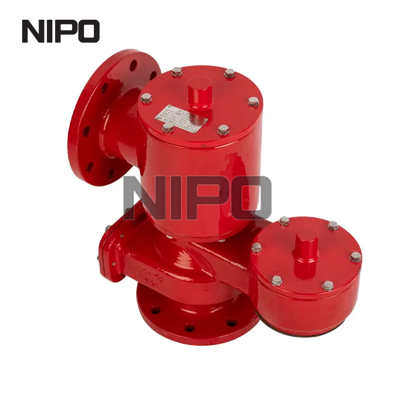
Chemical processing applications mandate specific material choices to ensure safety. Specifying a corrosion-resistant breather valve prevents premature mechanical failure. Standard aluminum or carbon steel degrades rapidly in aggressive environments. Galvanic corrosion eats away at dissimilar metals used in the assembly. Oxidation creates rough, pitted surfaces on the valve seats.
This ruins the soft seal and causes continuous, undetectable vapor leakage. Corrosive vapors from the stored product attack the internal components constantly. Hydrogen sulfide (H2S) in sour crude applications destroys aluminum internals in months. Coastal installations face relentless salt spray, attacking the exterior housing. Stainless steel provides a passive chromium-oxide layer that actively resists these chemical and environmental attacks.
Facility managers often weigh the upfront procurement of a stainless steel tank vent valve against cheaper alternatives. Aluminum and carbon steel require less initial capital. However, the long-term operational metrics heavily favor stainless steel construction. You eliminate frequent replacement cycles caused by corrosion.
Maintenance teams spend less time dismantling units to clean corroded seats or replace degraded pallets. You reduce unplanned downtime caused by seized pallets failing to open during pump transfers. The extended operational lifespan keeps the facility running without interruption. Furthermore, reliable sealing prevents continuous product evaporation, keeping valuable inventory inside the tank where it belongs.
Material Type | Corrosion Resistance | Temperature Range | Best Application Environment |
|---|---|---|---|
Aluminum | Low to Moderate | Standard Ambient | Non-corrosive, basic storage, lightweight needs |
Carbon Steel | Moderate (requires coating) | Standard Industrial | Non-corrosive hydrocarbons, dry environments |
316/316L Stainless Steel | Excellent | Extreme Cold to High Heat | Aggressive chemicals, marine, high-risk storage |
Extreme temperatures compromise standard alloys quickly. Carbon steel becomes dangerously brittle in sub-zero conditions, risking fracture under stress. Aluminum loses tensile strength rapidly at elevated temperatures. Utilizing a stainless steel breather valve maintains structural integrity across a massive temperature spectrum.
It resists embrittlement in extreme cold climates or cryogenic applications. It maintains its yield strength during high-heat process conditions. The higher molybdenum content in 316L stainless steel provides superior resistance to pitting and crevice corrosion, particularly in chloride-rich environments. This makes it the default engineering choice for demanding industrial applications where failure is not an option.
Storing flammable liquids introduces severe ignition risks. External fires, static discharge, or lightning strikes can ignite vented vapors outside the tank. You must specify a stainless steel flame retardant breathing valve for these highly volatile applications. These units feature integrated flame arrestors built directly into the venting pathway.
The arrestor element typically consists of tightly wound corrugated metal ribbons. It quenches the external ignition source by absorbing and dissipating the heat rapidly. This prevents the flame front from breaching the tank's internal vapor space. Proper engineering integration ensures the arrestor element does not restrict the required flow capacity of the valve. Technicians must clean these ribbon elements regularly to prevent fouling and flow restriction.
Large-scale storage facilities operate under strict regulatory and operational demands. Sourcing a stainless steel breather valve for oil depot storage requires absolute API compliance. These valves must integrate seamlessly with complex vapor recovery units (VRU). When the pressure pallet lifts, it routes the vapors into a closed header system rather than venting to the atmosphere.
The valve must handle the dynamic backpressure generated by the recovery system without fluttering. Engineers must verify that the selected seat materials and diaphragms withstand the specific hydrocarbon mixtures stored on-site, preventing swelling or degradation of the seals. A failed seal in a VRU system leads to cross-contamination and massive pressure imbalances across the tank farm.
Environmental agencies enforce strict limits on volatile organic compound (VOC) emissions globally. High-quality valves assist facilities in meeting EPA Clean Air Act requirements or local equivalents. They act as conservation valves during normal diurnal temperature cycles. By maintaining a bubble-tight seal until the exact set point is reached, they minimize daily vapor loss.
This conserves the stored product and prevents atmospheric pollution. Facilities must regularly document the leak rates of their venting equipment using EPA Method 21 or optical gas imaging cameras to avoid massive fines. Premium soft-seated stainless steel valves consistently test well below allowable emission thresholds, providing a reliable compliance mechanism for plant operators.
You cannot install these safety devices without rigorous testing documentation. Factory and field testing protocols ensure pressure and vacuum levels remain within safe operational limits. Technicians perform seat leakage testing according to API 2521 standards. They use specialized test rigs to apply incremental pressure and vacuum to the assembled unit.
Mount the valve securely to the calibrated test bench flange.
Apply pressure slowly until the pallet lifts, recording the exact set point.
Reduce pressure to 90% of the set point and measure the leakage rate using a flow meter.
Repeat the process on the vacuum side, pulling a negative pressure and recording the actuation point.
Document all findings and attach a certified calibration tag to the valve body.
This verifies the exact set point where the pallet lifts. It measures leak rates just prior to opening, ensuring the seal remains tight. Flow capacity validation ensures the unit meets the calculated API 2000 requirements. Regular field testing during turnarounds confirms the valve maintains its calibration over years of service.
Proper installation dictates operational success. You must mount the valve perfectly level on the tank roof. An angled installation causes the weight-loaded pallet to drag against the internal guide posts. This mechanical friction alters the set pressure and prevents tight sealing. Installers must avoid placing heavy piping strain on the valve flange when connecting vapor recovery lines.
Verify the tank flange is clean, flat, and free of deep scratches.
Select a compatible gasket material, such as a PTFE envelope gasket, to prevent chemical degradation.
Lower the valve onto the flange carefully, ensuring the weather hood does not strike the tank roof.
Tighten the flange bolts using a standard star pattern to ensure even gasket compression.
Apply the manufacturer-specified torque to prevent distorting the valve body.
Uneven bolt tightening distorts the valve body, ruining the precision seat alignment. Ensure all atmospheric pathways remain completely clear. Install heavy-duty bird screens to prevent wildlife from nesting inside the weather hood. Always remove all internal shipping blocks and protective tapes before commissioning.
Operational risks require proactive mitigation strategies. "Chattering" occurs when you install an oversized valve for the application. The valve opens, releases pressure instantly, and slams shut repeatedly. This rapid cycling damages the seats and destroys the pallets. You fix this by recalculating the flow requirements and installing a properly sized unit.
Freezing presents a major risk in cold climates. Moisture from the tank accumulates on the pallet and turns to ice, locking the valve closed. Mitigation strategies include installing steam jacketing or electric heat tracing around the valve body. Fouling happens when sticky vapors polymerize on the internal components. Specifying specialized pallet coatings like PTFE prevents this buildup and ensures smooth, reliable actuation.
A breather valve serves as a critical safety asset, not a commodity pipe fitting. The right valve protects multi-million dollar tank assets, secures sealed enclosures, and ensures strict environmental compliance. It prevents catastrophic structural failures caused by routine pressure fluctuations. The decision framework remains straightforward. Calculate your exact flow requirements using API 2000. Select materials based on vapor and environmental corrosivity. Integrate necessary safety features like flame retardants. Always verify manufacturer testing standards before procurement.
Compile complete tank data sheets, including physical dimensions, design pressures, and maximum pump rates.
Document all fluid properties, focusing on flash points, volatility, and chemical corrosivity.
Consult with a specialized piping engineer to run precise API 2000 sizing calculations.
Establish a routine inspection schedule based on the specific operational environment and local regulations.
A: Industry professionals frequently refer to them as Pressure/Vacuum Relief Valves (PVRVs). You will also hear them called conservation valves or direct-acting pressure/vacuum relief vents. The terminology often shifts depending on the specific industry, region, or engineering standards applied to the facility.
A: A breather valve handles both pressure and vacuum at very low settings, specifically designed for atmospheric tanks and sealed containers. Standard pressure relief valves (PRVs) typically handle high-pressure process systems and only relieve positive pressure, offering no vacuum protection.
A: Technicians use a specialized test rig to apply incremental pressure and vacuum to the unit. This process verifies the exact set point where the pallet lifts. It also measures leak rates prior to opening, ensuring the valve maintains safe operational limits without excessive emissions.
A: Stainless steel provides superior corrosion resistance and broader chemical compatibility. It performs exceptionally well in extreme temperatures and harsh marine environments. While aluminum is lighter, it degrades rapidly when exposed to corrosive vapors, leading to premature valve failure and leakage.
A: Common causes include debris trapped on the seat, degraded soft seals, and sticky product buildup. Improper installation can cause flange distortion, preventing the pallet from seating correctly. Incorrect set-pressure specifications can also cause the valve to actuate prematurely and leak vapors.
A: Standard industry timelines recommend comprehensive inspections every 1 to 3 years. However, this frequency depends heavily on the corrosivity of the service, the operating environment, and local environmental regulations. Highly aggressive chemical applications require more frequent maintenance checks to ensure reliability.
A: A breather valve prevents overpressure ruptures and vacuum implosions caused by normal operations. However, preventing explosions requires pairing the valve with a flame arrestor. The arrestor stops external ignition sources from traveling back through the vent and igniting the tank's internal vapor space.


