

close
Choose Your Site
Global
Social Media

Views: 0 Author: Site Editor Publish Time: 2026-09-03 Origin: Site


Incorrect venting capacity carries severe physical and financial consequences. A miscalculated venting system leads directly to catastrophic tank rupture from overpressure or sudden implosion from vacuum conditions. Plant engineers and facility managers face a constant operational challenge. You must balance strict safety compliance with daily operational efficiency. Minimizing fugitive emissions matters, but protecting capital equipment remains the top priority. Proper sizing is never a static guess. It is a dynamic calculation. You need a precise evaluation of tank specifications, fluid properties, transfer rates, and environmental variables. Only then can you select a specific valve configuration that guarantees long-term safety. We will break down the exact engineering steps required to size these devices accurately.
Accurate sizing requires calculating both thermal breathing (temperature fluctuations) and dynamic breathing (pump-in/pump-out rates).
Undersizing leads to catastrophic tank failure, while oversizing causes valve chatter, premature wear, and excessive fugitive emissions.
Standardized frameworks like API Standard 2000 dictate baseline venting requirements, but specific applications dictate the valve type (e.g., atmospheric vs. closed-loop).
When calculated venting capacity exceeds standard valve sizes, engineers must evaluate multiple-valve configurations rather than force-fitting undersized equipment.
Proper certification, flow testing, and equipment marking are non-negotiable steps for ensuring field compliance and long-term maintenance safety.
Define the primary objective clearly. A breather valve must maintain tank pressure within highly specific operating limits. These limits are the Maximum Allowable Working Pressure (MAWP) and Maximum Allowable Working Vacuum (MAWV). If internal pressure exceeds the MAWP, the tank shell ruptures at the seams. If internal pressure drops below the MAWV, the tank roof or walls buckle inward. Success means the valve opens exactly when needed. It vents enough volume to stabilize the internal pressure rapidly. It also closes tightly once normal conditions return. This tight seal prevents unnecessary product loss and stops fugitive emissions. We measure this success in standard cubic feet per hour (SCFH) or normal cubic meters per hour (Nm³/h).
Engineers sometimes estimate flow requirements based on outdated facility data. This leads to dangerous sizing errors with severe mechanical consequences. You must understand the failure modes associated with incorrect capacity calculations.
Undersized Valves: An undersized unit cannot relieve pressure or vacuum fast enough. During rapid pump-out, the liquid level drops quickly. If air cannot enter the tank fast enough, a vacuum forms. This leads to immediate structural deformation. During rapid heating, trapped vapor expands. If it cannot escape, pressure builds uncontrollably. This results in product loss through blown roof seals or catastrophic tank failure.
Oversized Valves: Bigger is rarely better in pressure relief. An oversized valve opens at the set pressure but quickly relieves the small volume of accumulated vapor. It then slams shut immediately. Pressure builds again rapidly, causing the valve to open and slam shut again. This rapid, violent cycling is called chatter. Chatter causes severe mechanical damage to the valve pallet and seat. It compromises sealing integrity permanently. This leads to continuous fugitive emissions and heavily increased maintenance costs.
Incorrect Set Points: Setting the opening pressure too close to the operating pressure causes continuous weeping. Setting it too close to the MAWP eliminates the safety margin. A sudden pressure spike damages the tank before the valve fully opens.
You must account for two distinct types of breathing to calculate total flow requirements accurately. These factors operate independently but often overlap during daily operations.
Thermal Inbreathing/Outbreathing: Ambient temperature changes drive constant vapor expansion and contraction. The sun heats the tank shell during the day. Internal vapors expand and require outbreathing. A sudden rainstorm causes rapid cooling of the tank shell. Vapors contract rapidly inside the tank. This sudden contraction requires massive inbreathing to prevent a vacuum.
Pump-Assisted Breathing: This is direct volumetric displacement. Pumping liquid into the tank displaces existing vapor. This action forces outbreathing. Pumping liquid out of the tank leaves a physical void. Air or blanketing gas must enter to fill this void. This action requires inbreathing.
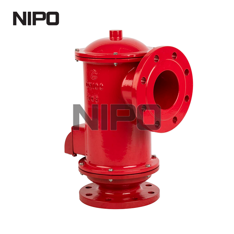
Start by documenting exact tank dimensions from the original engineering drawings. You need the diameter, height, and total internal volume. Record the design pressure and design vacuum limits. Next, identify the stored medium's chemical properties. You must know the flash point, boiling point, vapor pressure, and vapor density. These factors dictate exactly how volatile the fluid is under varying temperatures. Evaluate material compatibility carefully. The selected valve housing and internal seals must withstand corrosive or highly reactive media. Using incompatible materials leads to rapid seal degradation and premature failure.
Normal outbreathing combines two distinct operational factors. You add the maximum liquid filling rate (pump-in) to the thermal outbreathing rate (vapor expansion). Industry standards provide specific formulas for thermal expansion based on total tank volume. You adjust these baseline calculations based on the fluid itself. Volatile liquids generate significantly more vapor than non-volatile liquids when heated. Ensure your pump-in rate reflects the absolute maximum capacity of the transfer pumps, not just the average daily flow rate. If you upgrade your pumps later, you must recalculate the outbreathing requirements.
Normal inbreathing also combines two critical factors. Add the maximum liquid emptying rate (pump-out) to the thermal inbreathing rate (vapor contraction). The pump-out rate dictates how fast a vacuum can form mechanically. Thermal contraction usually peaks during sudden weather changes. A sudden drop in temperature causes rapid vapor condensation. This creates a severe, instantaneous vacuum demand. Your valve must handle the combined total of both events occurring simultaneously to protect the tank structure fully.
Normal operations do not account for external facility fires. If a pool fire surrounds the tank, the heat input is massive and sustained. This causes rapid, violent vapor expansion inside the shell. The required relief capacity far exceeds normal operational parameters. You evaluate this emergency venting requirement separately from standard breathing. Emergency vents often operate at a slightly higher set pressure than normal breather valves. This ensures they only open during an actual thermal crisis, preserving the primary valve's integrity during normal daily operations.
API Standard 2000 and ISO 28300 are the authoritative global frameworks. Engineers use them strictly for sizing venting devices on aboveground atmospheric and low-pressure storage tanks. These standards provide the exact mathematical formulas for thermal and dynamic breathing. They dictate how to calculate heat input during an external fire scenario. Following these standards ensures your calculations meet international safety benchmarks. They remove the guesswork from determining required flow rates. Compliance with these standards is often required by local safety regulators and insurance underwriters.
Regulatory compliance requires strict factory flow testing before installation. Manufacturers must verify acceptable leak rates before shipping any unit. Proper nameplate marking is a strict regulatory necessity. The metal nameplate must display the set pressure, maximum flow capacity, and relevant certification stamps. This ensures field compliance during safety audits. It also guarantees accurate replacement during future maintenance cycles. Never install a valve missing certified performance data or physical markings. Unmarked valves introduce unacceptable risk into the facility.
Large-scale chemical storage differs greatly from industrial hydraulic systems. Chemical tanks require complex API 2000 calculations involving thermodynamics. Hydraulic systems use a much simpler, practical approach. The industry rule of thumb for hydraulic tank breathers is straightforward. Divide the maximum pump rating in Gallons Per Minute (GPM) by 7.5. This calculation determines the baseline required airflow in Cubic Feet per Minute (CFM). This quick calculation ensures the hydraulic reservoir breathes adequately during rapid cylinder actuation, preventing pump cavitation.
You match calculated flow requirements and environmental risks to specific valve architectures. Use the table below to evaluate common configurations based on your specific site requirements.
Valve Configuration | Primary Application | Key Advantage | Common Limitation |
|---|---|---|---|
Atmospheric Venting | Non-toxic, non-flammable bulk storage | Cost-effective, simple installation | Releases vapors directly to the environment |
Pipe-Away System | Toxic, corrosive, or regulated VOCs | Captures emissions for downstream treatment | Susceptible to downstream piping backpressure |
Flame Retardant | Flammable liquids (e.g., ethanol, crude oil) | Prevents external flashback ignition | Requires regular cleaning of the arrester matrix |
Explosion-Proof | High-risk volatile environments (ATEX zones) | Withstands internal deflagration forces | Heavier construction requires stronger piping support |
Volatile environments demand specialized protection mechanisms. You must evaluate the necessity of an explosion-proof breather valve for ATEX or IECEx compliance. These robust valves withstand internal deflagrations without rupturing. They prevent structural failure during an explosive event, protecting surrounding infrastructure.
Additionally, assess the integration of a flame retardant breather valve. These units feature an integrated flame arrester matrix, often made of crimped metal ribbon. The arrester quenches flames attempting to enter the tank. This prevents external ignition sources, like lightning strikes or nearby equipment fires, from flashing back into the highly combustible vapor space.
Environmental regulations strictly limit atmospheric venting of toxic or noxious vapors. You must analyze the use of a pipe-away tank breather valve. This configuration routes hazardous vapors safely to a scrubber, flare, or vapor recovery unit. It prevents toxic release into the atmosphere, ensuring EPA or local environmental compliance.
When designing a closed system, evaluate the installation requirements for a breather valve with connecting nozzle. Focus heavily on flange standards and piping loads. Inlet and outlet piping design significantly impacts overall flow capacity. Poor piping design increases pressure drop. This pressure drop starves the valve of its rated capacity, rendering your initial sizing calculations dangerously inaccurate.
Sometimes, your calculated venting capacity exceeds the range of standard valve sizes available on the market. Do not force-fit an undersized unit to save space. Address this by utilizing multiple valves in parallel on the tank roof. Installing two or three properly sized valves ensures adequate flow capacity. Stagger their set pressures slightly during calibration. This prevents all valves from opening simultaneously during minor pressure fluctuations, which reduces mechanical wear across the system.
Pipe-away systems introduce a critical operational risk: backpressure. Routing vapors through long pipes, elbows, and chemical scrubbers creates physical resistance. This backpressure reduces the actual flow capacity of the valve significantly. You perform iterative calculations against manufacturer flow curves. If backpressure is high, you may need a larger valve to achieve the required flow rate at the specified overpressure. Ignoring backpressure leads to undersized performance in the field.
Setting the valve pressure requires a delicate engineering balance. If you set the pressure too close to the normal operating pressure, the valve will continuously weep. This causes constant fugitive emissions and unacceptable product loss. If you set it too close to the tank's design limit (MAWP), you reduce your safety margin drastically. A sudden pressure spike could damage the tank before the valve fully opens. Optimize the set pressure to provide a safe buffer on both ends of the operational spectrum.
Valves require regular inspection, cleaning, and seal replacement. The chosen size, weight, and piping configuration impact maintenance heavily. Consider the facility's ability to safely remove, test, and service the valve pallets and seats. Heavy pipe-away configurations require dedicated structural support. Plan for routine turnaround events early in the design phase. Ensure technicians have safe access platforms to perform in-situ testing without dismantling complex piping arrays.
Gather complete tank data sheets, fluid property profiles, and maximum pump transfer rates before beginning any sizing calculations.
Consult with a qualified process engineer to verify your API 2000 calculations against actual site conditions and local environmental regulations.
Calculate downstream backpressure carefully if utilizing a pipe-away configuration to ensure the selected valve meets the required flow capacity.
Request certified flow testing documentation and marked specifications from valve manufacturers prior to finalizing procurement.
A: You calculate the flow rate by combining dynamic and thermal breathing requirements per API 2000. Add the maximum liquid pump-in rate to the thermal vapor expansion rate for outbreathing. Add the maximum liquid pump-out rate to the thermal vapor contraction rate for inbreathing.
A: An oversized valve experiences rapid cycling, known as chatter. It opens, quickly relieves the small vapor volume, and slams shut repeatedly. This causes severe mechanical wear to the pallet and seat, leading to seal failure and continuous fugitive emissions at low flow rates.
A: You should use a pipe-away configuration when storing toxic, corrosive, or highly regulated volatile organic compounds. Instead of venting to the atmosphere, this valve routes hazardous vapors safely into a closed system, such as a scrubber, flare, or vapor recovery unit.
A: A flame retardant model integrates specific flame quenching elements, often a flame arrester matrix. If an external vapor cloud ignites, these elements absorb the heat and extinguish the flame front, preventing the fire from flashing back into the tank's volatile vapor space.
A: For hydraulic systems, a general guideline is to divide the maximum pump rating in Gallons Per Minute by 7.5. This provides the baseline required airflow in Cubic Feet per Minute. This rule applies strictly to hydraulic reservoirs, not chemical storage tanks.
A: Backpressure in the downstream piping creates resistance against the escaping vapor. This resistance significantly reduces the effective flow capacity of the valve. To compensate, engineers must iteratively check flow curves and often upsize the valve or adjust the set pressure to ensure adequate venting.
A: Certified factory markings guarantee the installed valve matches the exact calculated safety requirements for set pressure and flow capacity. Verified flow testing ensures the valve performs as designed. This documentation is critical for passing safety compliance audits and ensuring accurate replacements during future maintenance.


