

close
Choose Your Site
Global
Social Media

Views: 0 Author: Site Editor Publish Time: 2026-10-10 Origin: Site


A backfire flame arrestor is a mechanical safety barrier engineered to stop flame propagation from traveling backward into fuel-rich piping or storage tanks. When combustible gas ignites, the flame front accelerates rapidly through the system. Without immediate physical intervention, this backfire reaches bulk storage vessels or enclosed engine compartments, causing massive structural failure and severe safety hazards. Specifying the correct device requires balancing strict regulatory compliance across marine and industrial sectors with demanding operational efficiency requirements. Engineers and facility managers face the complex challenge of managing inherent pressure drops and flow velocities without compromising system safety margins.
This guide provides a rigorous framework for evaluating, sizing, and selecting the exact safety equipment required for specific applications. We examine the physical mechanisms of flame quenching and the structural differences between deflagration and detonation devices. You will learn how to navigate compliance standards, calculate pressure drop trade-offs, and implement maintenance protocols that ensure long-term operational integrity.
Compliance is Contextual: Requirements dictate that backfire flame arrestors must meet specific regulatory standards depending on the application (e.g., USCG for marine gasoline engines, API 2000/ISO 16852 for industrial facilities).
Deflagration vs. Detonation: Selecting between a standard deflagration arrestor and a detonation flame arrestor depends entirely on the piping distance between the potential ignition source and the arrestor, which dictates flame velocity.
The Pressure Drop Trade-off: The crimped metal elements required to extinguish flames inherently restrict flow; system design must account for this pressure drop to maintain operational efficiency.
Maintenance Dictates Lifespan: A flame arrestor is only effective if the element is free of fouling and corrosion. Strict inspection and cleaning protocols are mandatory implementation realities.
A backfire occurs when an unexpected ignition event forces a flame front to travel in the reverse direction of normal gas or vapor flow. In industrial piping or marine engine intakes, this reverse propagation is driven by the rapid expansion of combusting gases. Standard mechanical check valves or standard air filters completely fail to prevent this propagation. Mechanical valves close too slowly to stop a high-velocity flame front. Standard filters lack the thermal mass required to quench the combustion reaction. When flammable gases or vapors are present, the flame front consumes the available fuel, accelerating continuously until it reaches a larger fuel reservoir. A dedicated flame arrestor is explicitly engineered to interrupt this physical process by removing the heat necessary to sustain combustion.
The core component of any backfire prevention device is the flame cell. Manufacturers typically construct this from a tightly wound, crimped ribbon element. This element divides the main piping cross-section into thousands of microscopic capillary channels. The physics of flame quenching rely entirely on heat transfer. As the flame front enters the crimped element, the zigzag patterns of the metal mesh or fins force the burning gas to split into smaller streams.
The massive surface area of the metal absorbs the thermal energy from the combustion reaction. By rapidly transferring heat away from the gas stream, the metal element drops the temperature of the gas below its auto-ignition point. Once the temperature falls below this threshold, the chemical reaction of combustion can no longer sustain itself. The flame extinguishes instantly before it can exit the opposite side of the device.
The primary success criterion for these devices is limiting the velocity of a flame front to a safe, tested level while maintaining acceptable gas flow during normal operations. Industry standards strictly specify the maximum allowable velocity based on the specific gas mixture present in the system. To quantify this, engineers rely on the Maximum Experimental Safe Gap (MESG). The MESG is a standardized measurement determining the maximum clearance between two parallel metal surfaces that will prevent a specific gas flame from passing through.
Gases with high reactivity have a very small MESG and require extremely dense, tightly crimped elements to quench the flame. Gases with lower reactivity have a larger MESG, allowing for slightly larger capillary channels. The density of the crimped element directly impacts the pressure drop across the device. Success requires calculating the exact element density needed to stop the specific gas group while keeping the pressure drop below the threshold that would stall an engine or starve an industrial blower.
Gas Group (IEC/NEC) | Typical Reference Gas | MESG Value (mm) | Element Crimp Density Requirement |
|---|---|---|---|
Group IIA / D | Propane, Methane | > 0.90 mm | Standard density; moderate pressure drop. |
Group IIB / C | Ethylene | 0.50 mm to 0.90 mm | High density; significant pressure drop. |
Group IIC / B | Hydrogen, Acetylene | < 0.50 mm | Extreme density; highest pressure drop. |
Marine environments present unique explosion hazards due to the accumulation of volatile fuel vapors in enclosed hull spaces. The United States Coast Guard (USCG) enforces strict regulations, specifically 46 CFR § 25.35-1. This mandate requires backfire flame control on all enclosed gasoline engines installed after April 1940. If an engine backfires through the carburetor without a compliant arrestor, the escaping flame can instantly ignite stagnant bilge vapors, resulting in a vessel explosion. The USCG requires these devices to undergo rigorous testing to ensure they withstand repeated backfires without degrading.
A regulatory exemption exists for outboard motors. Because outboard motors mount externally and remain largely un-enclosed, fuel vapors dissipate directly into the open atmosphere rather than pooling in a confined space. Therefore, they are exempt from this specific backfire control requirement. However, for inboard and sterndrive engines, modifying factory-installed arrestors introduces severe legal and safety risks. Facility managers and boat owners must never alter the housing or route crankcase ventilation hoses remotely to bypass the arrestor. Remote routing creates an unmitigated ignition source, negating the safety certification and exposing the vessel to extreme explosion risks.
In industrial process safety, evaluation lenses are highly complex due to the continuous flow of volatile chemicals and varying pipe geometries. Compliance is governed by international standards such as ISO 16852, API Standard 2000, and ATEX directives. These frameworks dictate exhaustive testing protocols that devices must pass before installation.
Endurance Burning Test: The element must withstand a continuous flame stabilized on its surface for a specified duration without allowing flashback to the protected side.
Flashback Prevention Test: The device is subjected to repeated ignition events at varying pressures to ensure the crimped element maintains its structural integrity and quenching capability.
Flow Rate Verification: Manufacturers must provide precise data on flow rates and pressure drops, ensuring engineers can select a device that aligns perfectly with the specific hazards of their chemical processing facility.
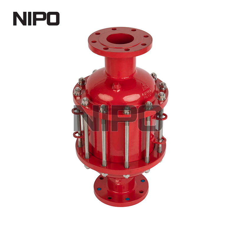
Deflagration refers to subsonic flame propagation, where the combustion wave travels slower than the speed of sound in the unburned gas. The flame is driven primarily by the thermal expansion of the burning gases. Deflagration arrestors handle these lower-velocity, lower-pressure events. End-of-line deflagration arrestors install directly at the atmospheric vent of a storage tank or process vessel. They prevent external flames, such as a lightning strike or external fire, from entering the tank.
In-line deflagration arrestors install within a piping system. Strict placement rules apply to in-line deflagration devices. They must be located very close to the potential ignition source. If the run-up distance—the length of pipe between the ignition source and the arrestor—is too long, the flame accelerates beyond the device's design limits, rendering it useless.
If a flame front travels through a sufficient length of pipe, the turbulence and pressure buildup cause the flame to accelerate rapidly. This acceleration triggers a Deflagration to Detonation Transition (DDT). Detonation is supersonic flame propagation accompanied by a massive, high-pressure shockwave. Standard deflagration elements will be instantly crushed by the kinetic energy of a detonation.
When piping configurations prevent installing an arrestor close to the ignition source, engineers must specify a detonation flame arrestor. These heavy-duty devices feature heavily reinforced housings, extended flame cell lengths, and robust structural supports. They are designed to absorb extreme kinetic energy, attenuate the shockwave, and quench the supersonic flame simultaneously.
Complex industrial facilities, such as vapor recovery units or flare gas headers, feature long, convoluted piping runs where flame acceleration is highly probable. In these high-risk scenarios, specifying an in line detonation flame arrestor is mandatory. Evaluation criteria for these specific applications focus on bi-directional protection capabilities. Because ignition sources in complex manifolds can originate from multiple directions, the device must be certified to stop a detonation approaching from either side. Engineers must evaluate the shockwave attenuation capabilities of the housing to ensure the physical impact of the detonation does not compromise downstream valves, sensors, or pipe joints.
Feature | In-Line Deflagration Arrestor | In-Line Detonation Arrestor |
|---|---|---|
Flame Speed | Subsonic (slower than sound) | Supersonic (faster than sound) |
Placement Constraints | Must be close to ignition source (Strict L/D limits) | Can be placed at extended distances from ignition source |
Structural Design | Standard housing, shorter flame cell | Reinforced housing, extended flame cell, shock absorbers |
Pressure Wave | Low to moderate pressure buildup | Extreme high-pressure shockwave |
The fundamental engineering challenge in specifying backfire prevention equipment is managing the relationship between the density of the flame cell and the resulting pressure drop across the element. To safely quench highly volatile gases, the crimped element must have very small capillary openings. These small openings inherently restrict the flow of gas, creating a pressure drop. Engineers analyze the pressure and velocity data provided by manufacturers to calculate the acceptable pressure loss.
If the pressure drop is too high, it starves marine engines of necessary intake air, causing rich running conditions and stalling. In industrial applications, excessive pressure drop forces blowers and compressors to consume significantly more energy to maintain required flow rates. A precise framework involves mapping the system's maximum flow rate against the manufacturer's flow curves to ensure the selected crimp size provides safety without destroying operational efficiency.
The long-term reliability of the flame cell and housing depends entirely on proper material selection tailored to the operating environment. If the crimped ribbon corrodes, the capillary channels widen, allowing flames to pass through, or they collapse, blocking flow entirely.
Aluminum is lightweight and cost-effective. It is suitable for standard marine engine intakes operating in freshwater environments where corrosion risks are minimal.
316L Stainless Steel is the baseline requirement for most industrial applications and saltwater marine environments. It offers excellent resistance to general corrosion and pitting from salt spray.
Hastelloy or other specialized alloys are mandatory when handling highly acidic industrial gases, such as hydrogen sulfide in biogas operations. Standard stainless steel degrades rapidly under these harsh chemical conditions.
Proper sizing extends beyond matching the pipe diameter. It requires strict adherence to the Length to Diameter (L/D) ratio rules defined during the device's certification testing. The L/D ratio dictates the maximum allowable distance between the ignition source and the arrestor. Installing the device outside this tested distance voids the safety certification.
Piping configurations heavily influence flame acceleration. Pipe bends, elbows, valves, and cross-sectional transitions between the ignition source and the arrestor create turbulence. This turbulence drastically increases flame speed. Engineers must account for these geometric constraints. A system with multiple 90-degree elbows often requires the specification of a more robust detonation device even if the straight-line distance seems short.
The transition toward decentralized power generation introduces complex gas mixtures that challenge standard safety equipment. A flame arrestor for gas distributed energy systems must handle varying compositions of biogas, syngas, and hydrogen blends. These operations present unique risks because the gas composition fluctuates based on the feedstock in anaerobic digesters or the output of electrolyzers.
Hydrogen possesses an extremely high burning velocity and a very low MESG. When hydrogen content increases in a distributed energy system, standard Group IIA or IIB elements become entirely ineffective. Engineers must specify highly specialized, tightly crimped Group IIC elements designed specifically to quench hydrogen flames. This ensures the system remains protected regardless of compositional shifts during daily operations.
In distributed energy storage and anaerobic digestion facilities, flame arrestors rarely operate in isolation. They pair with pressure/vacuum relief valves (PVRVs) to ensure holistic system safety. The PVRV manages the normal thermal breathing and operational pressure fluctuations of the storage tank. The arrestor sits beneath it to prevent external atmospheric ignition sources from entering the vapor space.
This integration requires careful calculation. The combined pressure drop of both the PVRV and the flame cell must be evaluated together. If the combined restriction is too high, the tank experiences dangerous overpressure or vacuum conditions during rapid filling or emptying cycles, potentially leading to tank rupture or implosion.
The most common point of failure in any backfire prevention system is particulate buildup within the crimped element. Because the capillary channels are microscopic, they act as unintended filters, trapping dust, dirt, unburned hydrocarbons, and process particulates. This fouling alters the pressure drop across the device, restricting flow and forcing system compressors to work harder.
Severe clogging reduces the cooling efficiency of the metal mass. If particulates accumulate, they create localized hot spots within the element during a backfire event. These hot spots retain enough thermal energy to cause auto-ignition of the gas on the protected side of the piping, resulting in a catastrophic bypass of the safety barrier.
Maintaining operational integrity requires a realistic, evidence-based maintenance schedule. Facilities must implement continuous monitoring of the differential pressure across the arrestor. A sudden increase in pressure drop is the primary indicator of element fouling. Cleaning procedures must be executed with extreme care.
Isolate and Depressurize: Safely lock out the piping system and ensure all hazardous gases are purged before opening the housing.
Extract the Element: Carefully remove the flame cell without striking it against the housing walls, which can dent the outer crimps.
Solvent or Ultrasonic Cleaning: Submerge the element in an approved chemical solvent or an ultrasonic bath. Never use mechanical wire brushes or high-pressure air blasts, as these bend the delicate crimped ribbons and destroy the quenching gaps.
Inspect for Damage: Hold the cleaned element up to a light source. If any capillary channels appear crushed, deformed, or corroded, the element cannot be repaired and must be discarded.
Reinstall with New Gaskets: Always use fresh OEM gaskets during reassembly to prevent fugitive emissions and ensure a proper seal.
Even the most robust detonation device fails if installed incorrectly. The primary installation risk is ignoring the certified L/D ratio distance from the potential ignition source. Field modifications, such as adding pipe extensions for easier maintenance access, push the device outside its certified run-up distance. This allows a deflagration to transition into a detonation that the device was not rated to handle.
Maintenance teams must strictly use OEM-certified replacement parts. Substituting a cheaper, non-certified element into a certified housing voids all regulatory compliance. It introduces unpredictable pressure drop and quenching characteristics into the safety system, putting the entire facility at risk.
Specifying a backfire flame arrestor is a highly technical engineering decision. It requires precise alignment between the specific gas composition, the exact piping geometry, and strict regulatory standards. Utilize simple deflagration arrestors for marine carburetors and short-run atmospheric vents, but escalate immediately to robust in-line detonation devices for extended industrial piping runs where flame acceleration is possible. To ensure total system safety and operational efficiency, execute the following steps:
Audit your current piping configurations to verify that all installed devices are within their certified L/D ratio limits.
Request specific flow, velocity, and pressure drop curves from manufacturers to ensure the selected element will not stall engines or starve blowers.
Implement a strict differential pressure monitoring schedule to detect element fouling before it compromises cooling efficiency.
Consult with a dedicated process safety engineer when handling variable gas mixtures, particularly those containing hydrogen or syngas.
A: The primary purpose is to prevent a flame front from traveling backward into a fuel-rich system, such as a storage tank or engine intake. It utilizes a tightly wound, crimped metal element to absorb heat, rapidly cooling the combustible gas below its auto-ignition temperature and instantly extinguishing the flame.
A: A deflagration arrestor stops subsonic flame propagation driven by thermal expansion. A detonation arrestor is heavily reinforced to stop supersonic flames accompanied by high-pressure shockwaves. The required type depends entirely on the pipe distance from the ignition source, which dictates how fast the flame can accelerate.
A: Under USCG 46 CFR § 25.35-1 regulations, they are legally required on all enclosed gasoline engines installed after April 1940 to prevent bilge explosions. Outboard motors are explicitly exempt from this requirement because they mount externally and do not trap fuel vapors in enclosed spaces.
A: Engineers calculate pressure drop by utilizing specific flow curves provided by the manufacturer. These calculations account for the gas density, the maximum system flow rate, the maximum allowable velocity, and the exact crimp size of the element required to quench that specific gas group.
A: No. Modifying the housing, altering the internal element, or remotely routing crankcase ventilation hoses instantly voids all safety certifications. These unauthorized modifications introduce severe explosion risks by creating bypass routes or establishing new, unmitigated remote ignition sources within the system.
A: The frequency of cleaning depends entirely on the particulate levels in the operating environment. Facilities must monitor the differential pressure across the device regularly. When pressure drop increases beyond baseline levels due to fouling, the element must be cleaned using approved solvents or replaced if deformed.


